Research Time reversal acoustic communication receivers
Abstract
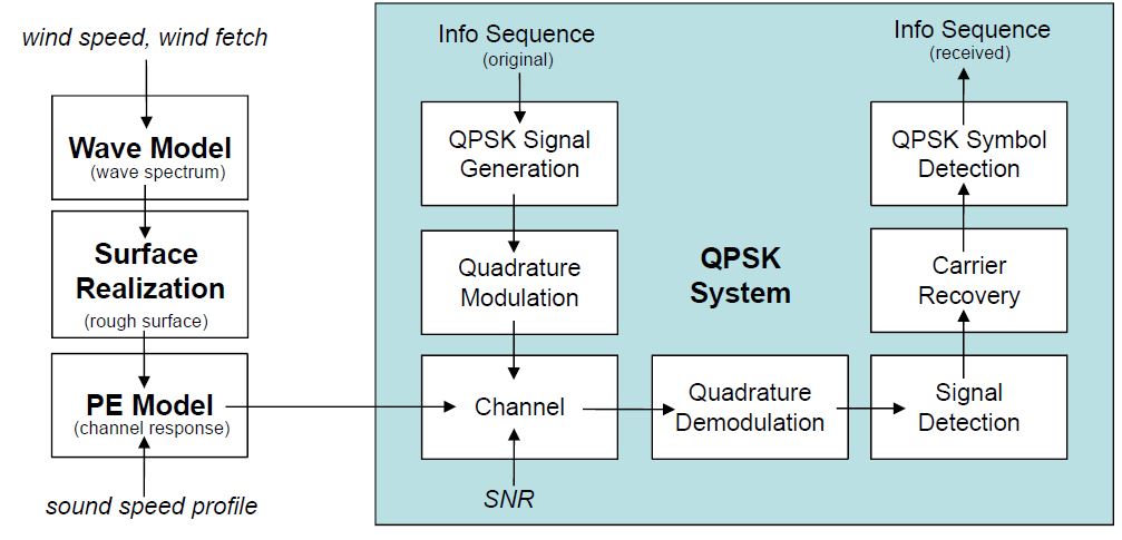
A communication system is implemented on digital signal processors (DSPs) for the underwater acoustic environment. The implemented receiver uses time reversal multi-channel combining followed by a single-channel decision feedback equalizer. Periodic channel estimation is employed to track the channel fluctuations. These techniques are used to mitigate time-varying inter-symbol interference, which is the main challenge in the underwater acoustic channel at operating frequencies greater than 10 kHz. Various optimization tasks are performed to reduce the receiver computational complexity. A fast implementation of the matching pursuit algorithm is tested on the DSP platform. Its performance, in terms of accuracy and run-time, is compared with that of the basic matching pursuit algorithm. Experimental results of the transmission and demodulation of binary phase-shift keying signals at three different symbol rates were obtained in the local Delaware Bay. The low bit error rates demonstrate the effectiveness of our implementation.
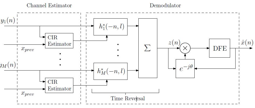
Consider a single-input multiple-output system which consists of one transducer and $M$ hydrophones. At the acoustic source, a binary symbol sequence $x(n)$ is modulated onto a carrier frequency $f_c$ and transmitted. The information signal propagates through the underwater acoustic channel, which introduces ISI, phase fluctuations, and ambient noise to the transmitted signal. On the receiver side, let $y_m(n)$ be the received baseband is modulated onto a carrier frequency $f_c$ and transmitted. The information signal propagates through the underwater acoustic channel, which introduces ISI, phase fluctuations, and ambient noise to the transmitted signal. On the receiver side, let $y_m(n)$ be the received baseband signal at the mth hydrophone. The effect of the UWA medium can be represented by a time-varying channel impulse response (CIR) $h_m(n, l),\ 0 \leq l \leq L − 1$ and $1 \leq m \leq M$, where $L$ is the discrete channel length. The received signal from a single source at the mth hydrophone can be written as:
$$y_m(n)=e^{j\theta_m(n)}\left[x(n)*h_m(n,l)\right]+v_m(n)$$
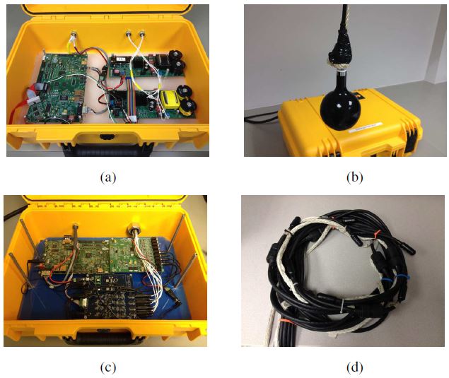
The receiver structure is shown in Fig. 1. It consists of a channel estimator and a demodulator. A pair of AMDPs were used for transmission and reception in our implementation. These are two programmable devices, shown in Fig. 2. The AMDP is controlled by an OMAP-L137 evaluation board, with a Texas Instruments OMAP-L137 as its main processor. The transmitter and receiver boxes operate on finite state machines (FSMs), which are provided by the vendor. Our implementation was programmed in C language on the OMAP-L137, in each state of the FSMs.
A non-sparse version of the CIR was obtained using the least squares algorithmand it is shown in Fig. 3. The signal power of channel 2 was lower than that of channel 8. In addition, channel fluctuations can be observed. For example, in Fig. 7(b), the CIR intensity changed during the geotime of 0.2 to 0.6 s. Similarly, in Fig. 3(f), the CIR intensity decreased around the geotime of 0.8 s, compared with that of 0.4 s.
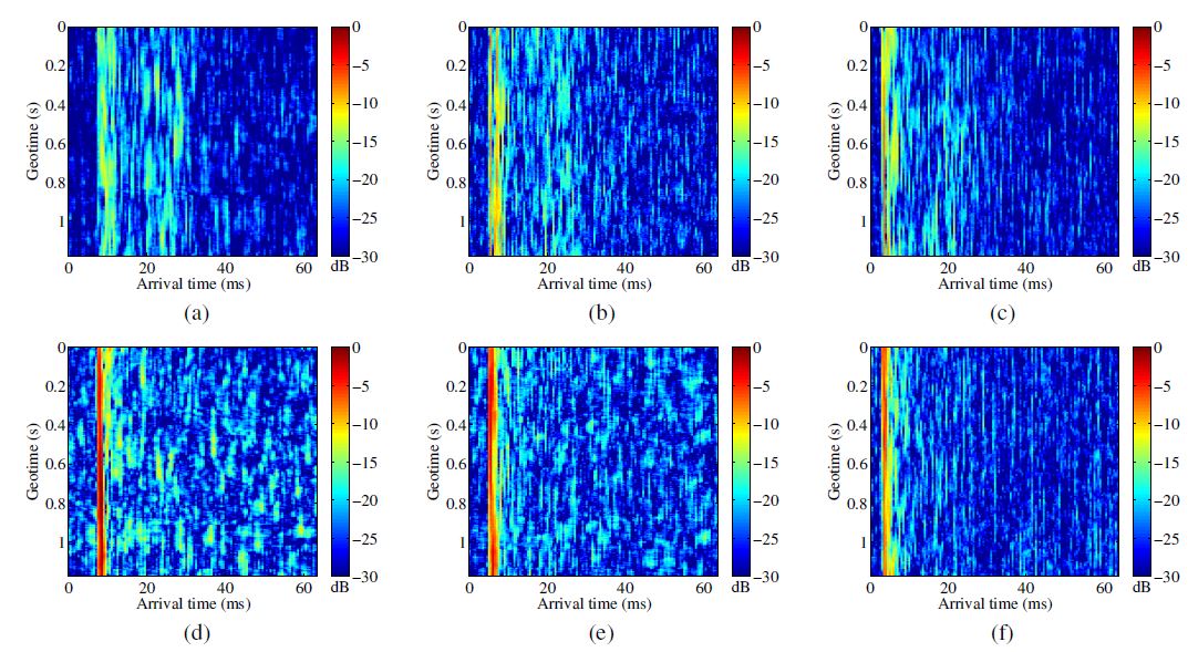
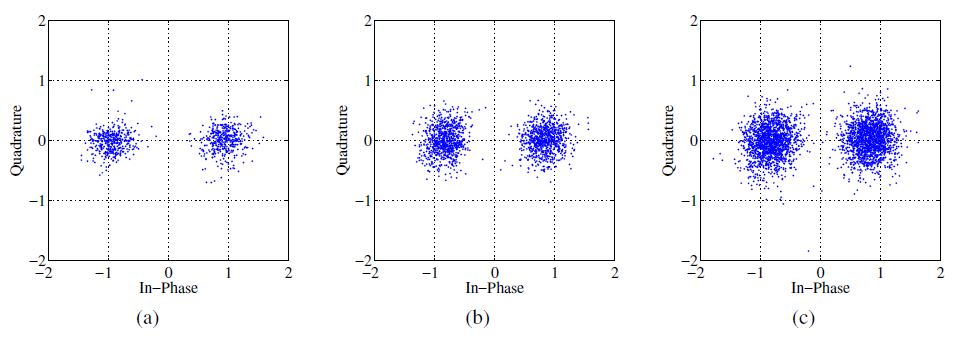
Fig. 4 shows the scatter plot of the demodulated symbols at the three different symbol rates when TR-DFE was used. The spread of the demodulated symbols increases as the symbol rate increases, which is consistent with the output MSE.
We have implemented high frequency time reversal receivers on a DSP platform for the UWA environment. The architecture and functioning of the communication system over the hardware platform have been presented. In addition, several optimizations have been described. The field experiment demonstrates that these techniques effectively reduce the execution time of the receiver. The FMP algorithm, as a fast implementation of the BMP algorithm, has been introduced and tested on the DSP platform. In comparison with the BMP algorithm, it has been shown that the FMP algorithm is more suitable for DSP implementations, due to a lower complexity and a similar level of accuracy. The low BERs obtained during our experiment at the different symbol rates demonstrate the effectiveness of our DSP implementation.
Related publications
-
Time Reversal Acoustic Communication Receivers: DSP Implementation and Fast Channel Estimation
Sergio Matiz Romero, Mohsen Badiey, and Aijun Song. DOI: 10.1016/j.phycom.2016.02.002. [PDF]
Related conferences
-
Preliminary estimates of year-round acoustic communications potential in the Canada Basin
Carolyn Binder, Sean Pecknold, Mohsen Badiey. DOI: 10.1121/1.5136565