P2B Modification Guide (several other sorts of modifications to that board, such as improved processor support and more frequencies)
Introduction: nature of the failure
According to Asus Technical Department and published to news://news2.asus.com.tw/asus.support.english.mainboard.p2bx, there is a design flaw in Asus motherboards P2B-LS, rev. 1.02 and older. This flaw, an out-of-specification voltage applied to one of the CPU's pins, causes the system to become unstable or more likely hang, when the load of the CPU is heavy, such as when processing large images in Photoshop. In my particular case, the system would freeze simply by performing a disk scan for errors or by running two or more instances of Internet Explorer for a long time. Maybe this exaggerated instability was due to the fact I have two video boards running simultaneously.
Again according to Asus, the fix involves adding a 10µF or 22µF polarized capacitor on the back side of the motherboard, on the slot 1, between +1.5V Pin and Ground Pin. With the valuable help of Michael Smola, who posted his experiences to the newsgroup, I was able to locate the proper pins and do the rework myself.
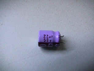
The rework is basically soldering the capacitor between pins A1/A3 (which are connected together in the Asus board) and pin A2. Pin A2 is the Ground reference (negative), and pins A1/A3 are the +1.5V VTT (positive). Michael Smola used a 22µF Tantalum Capacitor in his job, since it is small and has good RF parameters. I intended to use the same type, but the salesman at the electronics shop did me the favor of selling me a .22µF Tantal capacitor, instead of the proper 22µF. As I was too excited to perform the rework, I decided to experiment with a 22µF electrolytic capacitor I had in my components' drawer. Here is a picture of it.
|
|
|
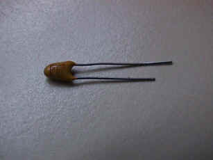
| Electrolytic Capacitor | This is how a Tantalum capacitor looks like |
Notice that the electrolytic capacitor on the left is a 50V one. Anything above 35V should be safe to be used in this rework, or at least capacitors of the same voltage as the original ones soldered to the top of the Asus motherboard.
Since this capacitor is somewhat big, I needed to connect it to the back of the board using wires, so that the capacitor could rest on top of the motherboard. If your capacitor is small enough and you are a skilled with the soldering gun, the capacitor can be connected itself to the back of the board, eliminating the need for wires (which electronically speaking, are not recommended). As a matter of fact, the use of wires is not recommended, since they act as RF antennas, thus bringing noise into the system. Should you use wires, make sure you keep them as short as possible.
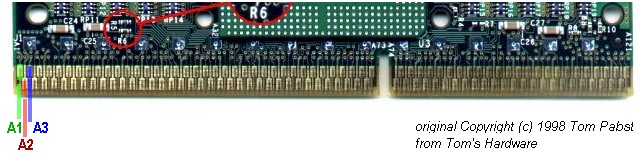
The pins involved are A1, A2 and A3 of Slot 1. In the Pentium II they face the heatsink and the fan, left side. The mark "A1" can be located by looking the gold plated pins carefully, even though Pentium II's are cased.
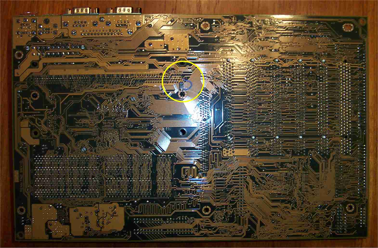
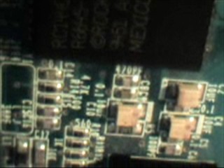
On the back of the motherboard, the pins are located to the front of the board, following the same disposition as the gold plated pins on the CPU. The picture below shows the motherboard on its back, after the rework. Note the wires coming out of the Slot 1 and to the top of the board.
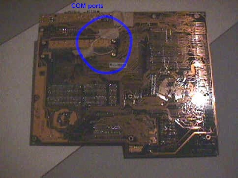
P2B-LS motherboard, back side (already reworked.
Note the wires at the top. In this picture, they are long, but they were
considerably shortened afterwards.)
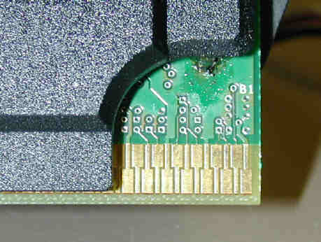
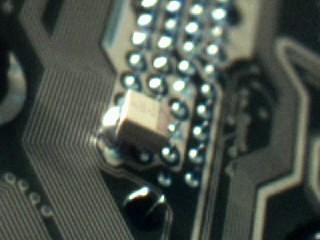
The pictures below show the wires connected to pins A1/A3 (VTT) and pin A2 (GND). The positive (+) terminal of the capacitor goes to pins A1/A3, and the negative (-) terminal of the capacitor goes to pin A2.
Note that the pins located above are the "B" pins (B1 to B121). In the pictures below, it might seem that the black wire goes to pin B121 (located above and to the right of pin A2), put that's false. It is soldered to pin A2.
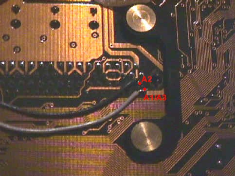
Detailed vision of pins A1/A3 and A2, with a wire
connected to each.
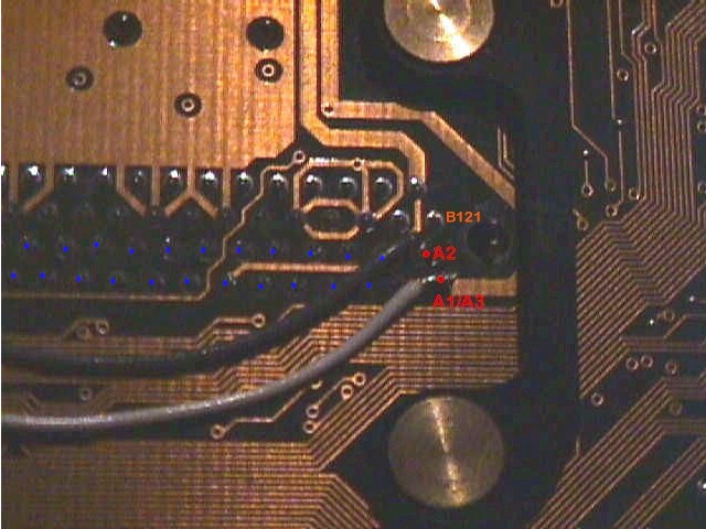
Another picture with the wires connected in detail
Michael Smola also recommends combining the 22µF capacitor with a ceramic capacitor of approx. 100nF for RF blocking, as theory states. I didn't do it, but the whole reworking process was successful.
After the rework, I submitted the machine to several tests. I performed the same operations that resulted in crashes, opened several windows simultaneously and ran computational intensive programs, such as graphics ones. The system was perfectly stable. Hence, the whole reworking process could be considered successful. Since then, I have received reports from several people who also performed the rework themselves, and all of them were rewarded with stable systems afterwards.
This page brings several modifications that can be performed on the P2B, P2B-D, P2B-L motherboards. Those include upgraded processor support, more frequencies, changing voltage to the processor, building heat sensors and more.
A rework procedure for the Asus CUBX, when suffering from the same crashes and freezes described above, is provided by Christian Buess at http://members.ams.chello.nl/mgherard/html/photoshop.html. An excerpt of that page is show below.
"I thought you might be interested in the rework I did with my CUBX board.
Through your good Web site I learned that the CUBX board experiences
locks/crashes when using PhotoShop 5.5
I also have (had) that problem on my computer, and as I use PhotoShop a lot I
had to find a solution.
The fix presented by Adobe (removing the 'Extensions' folder) helped, but it
reduces performance...
The PhotoShop problem also happens on P2B.. and P3B.. boards from ASUS.
(...) I learned that the PhotoShop crash is caused by a transient (spike) on the
VTT termination voltage for the AGTL+ bus of the PentiumIII.
After downloading the documentation for the PentiumIII (FCPGA and SECC2 package,
here) I decided to
do a similar rework on my CUBX board.
The attached picture shows the rework I did: Fortunately the VTT plane is on the
back side of the CUBX board. This makes rework a little bit easier.
I
added the following components:
1) A 10uF (mikro Farad) polarized tantalum capacitor between VTT (pin AN11) and
VSS(ground, pin AM10),
2) a 100nF (nano Farad) capacitor between VTT (pin AN15) and VSS (ground, pin
AM14)
3) a 100nF capacitor between VTT and VSS below the main capacitor for VTT.
The tantalum capacitor is used in addition to the main decoupling capacitor of
100uF located on the CUBX board.
The two additional 100nF capacitors should additionally reduce high frequency
(HF) spikes on VTT.
According to my understanding it is important that the capacitors are mounted
with VERY short wires - this improves HF performance a lot. As the voltage on
VTT is only 1.55 V, the voltage rating of the capacitors is not critical.
The nice thing: After doing the rework there were no more crashes with
PhotoShop!!
Now I am really happy with my CUBX board!! I think I have to mention that this
rework should only be done by experienced users!
It is not an easy job to do the soldering - you have to be very careful and you
have to have an appropriate soldering iron!
But on the other hand it really helps..."
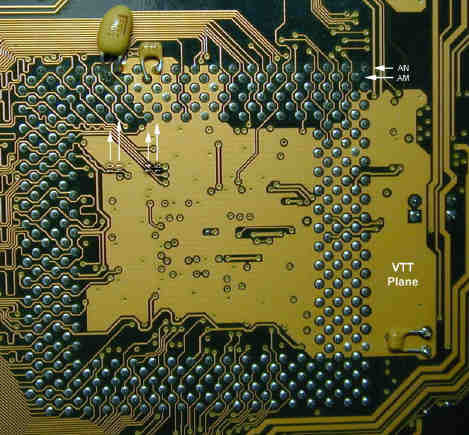
CUBX, VTT (back) plane with capacitors soldered.
Four different fixes are shown below.
Adding a capacitor to location CE33 on motherboard
This fix, provided by Keith Barnes, consists of adding a 100μF 16V capacitor to the location tagged CE33, on the left corner of the CPU slot. Here is Barnes' report:
"What
I did was remove my motherboard. I found the CE33 location on the
board. Seemed to be an unused capacitor location. It was marked and had
a + marking (positive side marked). There was solder in the holes. So I
did not use any additional solder. I used a 30 watt soldering pen and
heated up the hole on the back side of the board (not on cpu slot side).
And while it was hot I inserted one lead of the capacitor and then the
other into the holes on the cpu slot side. It worked and Photoshop 5.5
no longer crashes."
Depending on the rev. number of the P3B-F, you may encounter a capacitor already at the CE33 location. If so, proceed to the next fix. The picture below shows the CPU slot on the P3B-F with all capacitors installed.
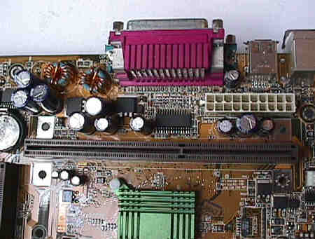
P3B-F rev. 1.04. Capacitor on CE33 is
already installed from factory.
Loek van Schie, from Delft University of Technology, Netherlands, reported success after installing a 6.8μF capacitor directly on the CPU circuit board. He used the same pins as described on the P2B-LS rework, so the capacitor can be soldered to the motherboard as well. This is basically the same P2B-LS rework, but with a different capacitor value. Schie's report:
"I have 12 PC's running in our lab at Delft University with ASUS P3B-F mainboards. OS is dualboot Linux/NT4. Opening pdf-files with a lot of graphics and also MPEG and FLASH applications caused the PC's freezing. The systems were delivered at jan. 2000 and worked fine. However last year I got more and more complaints about freezing. So I inspected one system and couldn't find anything wrong. I changed all the hardware (except mobo) with other components but no difference. There is still one year guarantee on the systems so I brought one system back and they replaced the mobo with a new P3B-F and gone were the problems. But this motherboard is not available anymore and the slot1 CPU is another problem. I decided to try the trick with the capacitor and it worked. I did not want to remove all the mainboards so I soldered a 6,8µF capacitor direct on the CPU-pcb. The capacitor must not be to thick for fixing between the pcb and plastic cover."
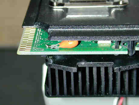
Capacitor soldered directly to the CPU pcb, using
same pins as P2B-LS rework.
Using a 22μF Tantalum capacitor
Toni Verdu Carbo, from Universitat de Girona, Catalunya, Spain, reported having success reworking the P3B-F by installing a 22μF capacitor directly to the CPU pcb, just as described above, instead of the 6.8μF one. His P3B-F already had the CE33 capacitor installed from factory. The installation was made by soldering the capacitor pins to the copper connections on the pcb, after scraping the green protection.
Installing the capacitor to the back of the motherboard
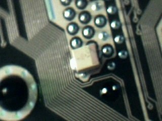
Here is a picture of the fine rework performed by Chris Gardner, from Dallas, Texas, USA. Notice the small capacitor soldered between pins A1/A3 and A2, with the help of a short blue wire. A 10μF or 22μF capacitor should perform conveniently. Click on the picture for a larger version.
Below is the fix performed by Corey Thompson (Canada?), who used a 10μF surface mount tantalum capacitor recycled from an old modem, soldered to the back of the slot 1 to pins A1/A3 and A2. Soldering that small capacitor must have been a tricky job, but it reestablished the motherboard stability (running Debian Linux).
 |
 |
 |
|
Another fix to the P3B-F rev. 1.04 was reported by Nick Kooij, from Toronto, Canada. His board had no capacitor installed at CE33. He attempted soldering a 100μF 16V electrolytic capacitor to those pins, but the lockup with Photoshop continued. So, he soldered a 10μF 25V electrolytic capacitor (rescued from a trashed sound card) to pins A1/A3 and A2 directly to the back of the board. This, he informed, fixed the instability problem, bringing the P3B-F out of retirement and back to service.
If you have reports and experiences on another rework, drop me a note.
Asus original message, published in their newsgroups (long ago deactivated)
This text was obtained from an internet database. No lawsuits on me please. :)
"Dear Sir,
This is a known problem for us. It's caused by the CPU undershoot of +1.5V
is over the Intel Spec when the CPU loading is very heavy. And it will
incur
the system become unstable even hung up.
We found that at ealier July and had fixed it after that.
Rework Method :
# P2B-DS :
1. Change Q8 from 2sd1802 to RFD3055
2. Change CE14 from normal 1000uF to Higher Height 1000uF Capacitor.
# P2B-LS :
Add a new 10uF or 22uF Capacitor on the back side of Slot 1 between 1.5V &
GND.
This issue only happens when very heavy CPU loading like the photoshop need
a huge CPU loading for the image access.
If you request, please send the problemed boards back to our RMA center for
reworking through your vendor.
Sorry for any inconvenience.
Best Regards,
ASUSTeK Technical Support Division
For marketing -> info@asus.com.tw
For Web -> webmaster@asus.com.tw
For technical info -> http://www.asus.com.tw/Company/support-news.html"
|
|
| Home |
