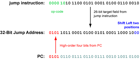
The Jump Instruction
In
our schematic programs, the "jump" instruction
loaded the PC with a 32-bit address.
How does a 32-bit instruction specify a 32-bit address?
Some of the instruction's bits must be used for the op-code.
Here is the assembly language form of the jump instruction.
j    target     # after a delay of one machine cycle,
                # PC  <-- address of target
Here is the machine language form of the instruction:
   6              26
000010 00000000000000000000000000    -- fields of the instructuion

opcode         target                -- meaning of the fields
There
is room in the instruction for
a 26-bit address.
The 26-bit target address field is
transformed into a 32-bit address.
This is done
at run-time,
as the jump instruction is executed.
Instructions always start on an address that is a multiple
of four (they are word-aligned).
So the low order two bits of a 32-bit instruction address
are always "00".
Shifting the 26-bit target left two places results in a 28-bit
word-aligned address
(the low-order two bits become "00".)
After the shift, we need to fill in the high-order four bits
of the address.
These four bits come from the
high-order four bits
in the PC.
These are concatenated to the high-order end of the 28-bit address
to form a 32-bit address.
For example, here is the machine language for the
instruction that jumps to location 0x5B145188.
Say that the instruction is located at
address 0x56767250.
