Lorentz force law (right-hand rule) Current flowing perpendicular to a magnetic field experiences a force perpendicular to both the current and the magnetic field. If the the fingers of the right hand curl from the direction of the (positive) current to the direction of the magnetic field (from N to S pole) the thumb points in the direction of the force.
Lorentz force law how motors work
Kinds of motors: D.C., A.C., Stepper.
A coil in a magnetic field will rotate until its magnetic field lines up with the provided magnetic field. (Draw picture.)
Magnetic field can be provided by permanent magnets or by field coils around iron cores. The rotating coil(s), called the armature, may or may not have an iron core. (Core is left out if maximum rotational speed is needed.)
To get continuous rotation, a commutator is used; brushes automatically switch the driving current to the direction that will continue the rotation.
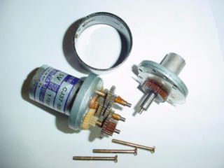
Inside a toy motor part I Inside a toy motor part II
[There is a brushless type of D.C. motor that has the permanent magnet in the armature and the driving current goes to field coils. The currents in these coils have to be switched on and off electronically by transistors in time with the rotation of the permanent magnet.]
App Note on brushless DC motor fundamentals (note similarity to stepper motors below)
D.C. motors often have gears attached to them to provide more turning force at a lower speed of rotation. These motors are called DC gearhead motors.
Torque = angular force that a motor can deliver at a certain distance from its shaft.
Examples: 5 oz-in of torque means that a 5 oz weight can be lifted by a string that wraps around a motor shaft that is 1" in radius.
Newton-meters (Nm). (1 Newton approximately = the weight of an apple!)
Gram-force-centimeters (gf-cm). 1 gram-force = weight of 1 gram of mass.
               2
1 N = 1 kg-m/sec  = 0.225 lb = 0.101972 kilograms (force)
1 kg = 2.21 lb (mass)
1 in = 2.54 cm

Power = energy/sec

1 Watt = 1 Joule/sec

Let

Pe = electrical power (into motor)

Pm = mechanical power (out of motor)

V = voltage

I = current

R = winding resistance

e = back-emf (emf = electromotive force)

T = torque of motor

omega = angular speed        (omega = w)

eta = coversion efficiency   (eta = n with long second leg)

Is = starting current or stall current

ke = back-emf constant

kt = torque constant


The following relationships hold by definition:


Pe = VI                                                             (1)

Pm = T omega                                                        (2)

2 pi radians/sec = 1 revolution/sec

1 Watt = 1 Nm/sec
Some energy is lost in the motor, so Pm = eta Pe  (eta < 1)         (3)

Since the motor winding is rotating in a magnetic field, it acts as a generator
generating a back-emf.  This is a voltage source in series with the winding
resistence R.

The motor is described by the equation

V = IR + e
                                                                    (4)
When the motor is not rotating, the maximum current can flow (e = 0), so

Is = V/R                                                            (5)

When the motor is rotating, e = ke omega.                           (6)

Therefore, (from (4) and (6))

V = IR + ke omega                                                   (7)

When the motor is in a steady state (turning at a constant speed), torque
is proportional to current:

T = kt I                                                            (8)

Since the output power is the input power minus the power lost as heat in
the winding resistance,
           2
Pm = Pe - I R                                                       (9)

Substituting from previous equations, (from (1), (2) and (9))
                 2
T omega = V I - I R                                                (10)

Replacing T and V, (from (7), (8) and (10))
                                 2
kt I omega = (IR + ke omega)I - I R                                (11)

which reduces to kt = ke.  Call this constant k.  Then we have
(from (7), (8), kt = ke = k)

V = TR/k + k omega                                                 (12)

or
              2
omega = - (R/k )T + V/k                                            (13)


Since Pm = T omega, we have (from (2) and (13))
            2   2
Pm = - (R/(k ))T  + (V/k)T                                         (14)

When graphed, this is an upside-down parabola going through the points
(0,0) and (Tmax,0).  Maximum power will occur at 1/2 of Tmax.

The maximum angular speed will occur with T = 0 and no load: (from (13))

   omega-max = V/k                                                 (15)

When the motor stalls,  (from (5), (8) and kt = k)

Ts = k Is = kV/R = Tmax.                                           (16)


Since Pm is max when T = 1/2 Tmax, (from (14) and (16))

          2
Pm-max = V /4R                                                     (17)


We solve for omega and find that when Pm is max,
(from (2), T = Tmax/2, (15), (16) and (17))

omega = 1/2 omaga-max                                              (18)
At maximum power , Pm = 1/4 omega-max Tmax. (from (2), (16) and (18))
Maximum efficiency occurs when
                              2
   eta-max = (1 - sqrt(Io/Is))
where Io = no-load current.
Cheap motors are likely to have a maximum efficiency of about 50%.
Gear trains can be spur gears, planetary gears (gears in an outer ring), worm gears, lead screw and nut, rack-and-pinion, and belt-and-pulley.
Futaba FP-S148 Servo used as a motor.

Specs:

Weight             1.5 oz (44.4 g)
Output Torque      42 oz-in  (3kg-cm)
Power Consumption  6.0 V 8mA (at idle)
Operating Speed    0.22 sec/60 degrees

Operating speed translates to 46 rpm:

60 degrees/0.22sec * 2 pi radians/360 degrees = 4.8 radians/sec = 46 rpm.

or more simply,

60 degrees/0.22sec * 1revolution/360 degrees * 60 sec/1minute = 45 rpm.

Output Torque in Newton-meters:

42 oz-in * lb/16 oz * 1N/0.225 lb * 2.54 cm/1 in * 1 m/100 cm = 0.296 Nm

or in SI units,

3 kg-cm * 1N/0.101972 kg * 1m/100cm = 0.294 Nm

(The differences in the two Nm and rpm values are due to accumulated round-off
errors.)

Max possible power is

Pm,max =  1/4 Tmax omega-max = 1/4 * 0.296 Nm * 4.8 radians/sec = 0.3555 W
Often done with an H-bridge

                            Vs
            +-----+---------+-----------+-----+
            |     |                     |     |
          |/     ---                   ---     \|
    A--R--|v      ^                     ^      v|--R--B
            |     |                     |     |
            +-----+-----H< motor >H-----+-----+
            |     |                     |     +
          |/     ---                   ---     \|
    B--R--|v      ^                     ^      v|--R--A
            |     |                     |     |
            +-----+---------+-----------+-----+
                            Gr
(Points A are connected together and points B are connected together.)

Motor turns forward when A is high and B is low.
Motor turns backard when B is high and A is low.
The diodes are called flyback diodes. They provide a path for the current that is produced by the motor when power to the motor is cut off, protecting the transistors from being burned out. A flyback diode is also connected across the coil of a relay to prevent the back emf that is produced when the current through the coil is suddenly cut off from burning out the rest of the circuit.
Brief theory of operation H-bridge in bottom half of page another H-bridge
Speed controlled by Pulse Width Modulation. (Less power loss in circuits.)
H-bridges are available as IC chips.
Two kinds, single-phase, three-phase. rotating field (click on right arrow 10 times) inside a 3-phase AC motor (click on right arrow 6 times)
Note: Normally, 3-phase AC motors get their power from the power station as AC delivered over three power lines but with the three lines 120 degrees out of phase with each other. (This AC power is generated by a 3-phase generator at the power plant.) It is possible to run a 3-phase AC motor on a single phase power system (the normal distribution for homes), but capacitors are temporarilly connected to the motor to get it started or a rotary phase converter is used to create 3-phase AC output. The converter is a 3-phase AC motor connected with capacitors to the 3-phase lines going to the main motor. It is powered by the single phase power lines and through the capacitors creates a third power line in different phase from the other two. A third approach is to rectify the AC power into DC, then generate 3-phase power from the DC with electronic circuits.
AC motors can be cheaper, more rugged, reliable, maintenance free. But when speed control is added, they are generally more expensive than DC motors with speed control.
stepper motors Click on the gifs for both Figure 1.1 and Figure 1.2.
Variable reluctance steppers four pole soft steel rotor, six pole stator (three pairs of electromagnets--two rotor poles align with magnetic field of the active electromagnet)
Permanent magnet steppers
rotor is a permanent magnet, stator is two electromagnets (each has
two poles);
position controlled by turning on or off and changing the current
direction to one or both electromagnets
In both cases, by turning off/on or reversing appropriate field coils, the armature can be made to rotate a fixed number of degrees to the next stable position.
Servo motors have a motor that turns the shaft of a potentiometer. The control signal is a pulse, the width of which is converted into a voltage. This voltage is compared to the voltage at the slider of the potentiometer. The difference determines which way the motor turns and how fast. The motor stops when the shaft is in the position that equalizes the two voltages.
How RC servos work Two useful documents One is all about servos, the other shows the inside of a servo. (Click on Search.)