Moser 12bolt Rear on a Thirdgen Z28 w/427sbc and T56 6-speed
This test examines my 427cid motor with a TPIS MiniRam intake
The current engine is a 4.125 bore x 4.000 stroke short block,
with the buildup described here.
The trans is upgraded to a T56 from a 1995 camaro. The exhaust is
Hooker Longtubes (2210s) and a custom exhaust. Dual electric cutouts
are mounted behind the header collectors and the the duals continue to
a 4inch Y-pipe that reduces to a 3" over-axle pipe to a Dynomax muffler.
These tests are on a new Moser
12-bolt . The 12bolt is equipped with a 3.42 gear ratio (down
from a 3.73 ratio in the previous 10bolt) and a TruTrac differential.
This gear and differential selection was based upon the Road Course nature
of the car now. An online reference listed a 8% RWTQ loss should be
expected by going from a 3.73 ratio down to a 3.42 ratio, and an
additional lose from going from the smaller 7.5inch ring gear of the 10bolt,
to the 8.75inch ring gear of the 12bolt.
The DynoJet Dyno is located in:
Newark, DE
-
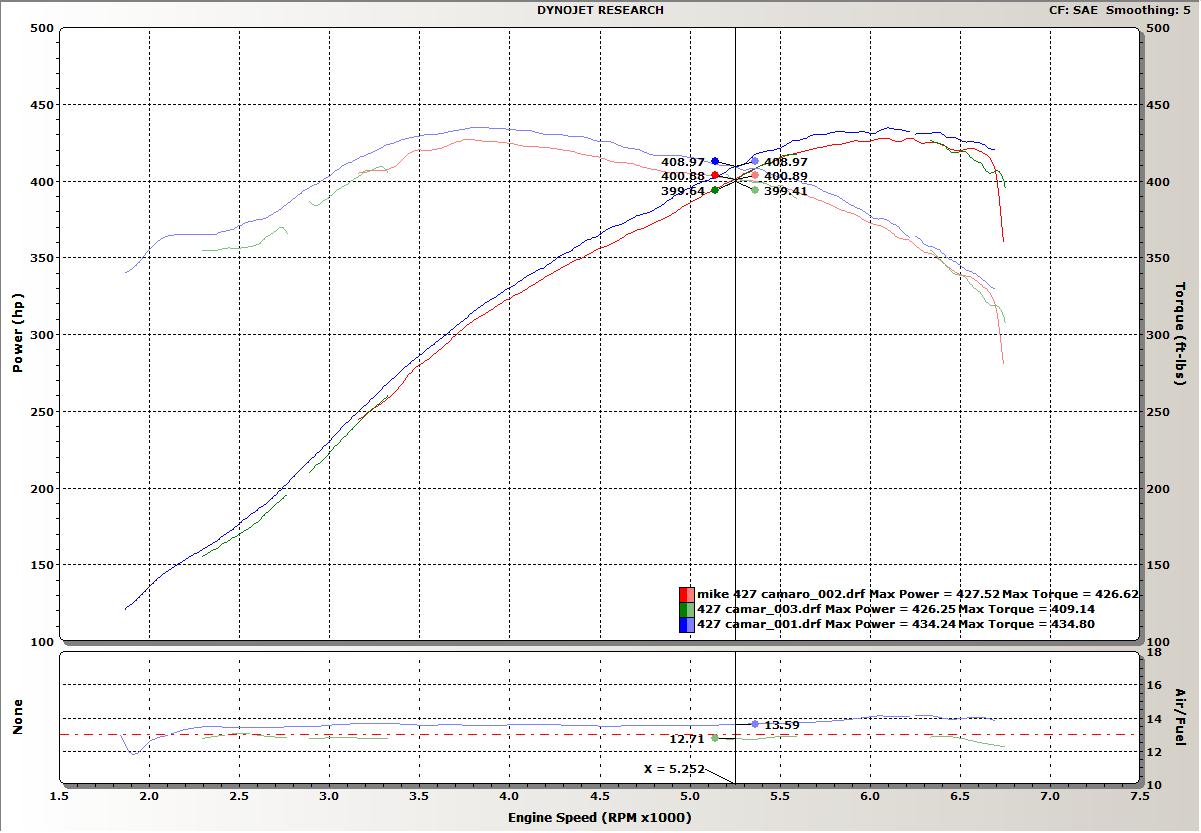
These 3, full-exhaust, runs are (Red) best 10bolt baseline, (Blue) First
12bolt test, tuning AFR, and (Green) final 12bolt with tuned AFR.
(Note the Green run is mostly missing because of problems with the RPM
pickup during this dyno session)
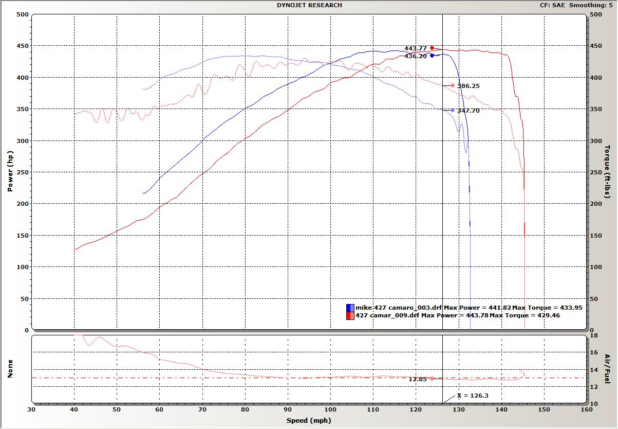
This graph shows the open-exhaust (dump pipes open) runs from the (Blue)
10-bolt w/3.73s, and the (Red) 12-bolt w/3.42s. The graph is shown
in MPH because the RPM
pickup was having trouble recording properly during many of these current
tests. (The lean AFR readings were because the dumps were open before where the WB sensor was sampling)
Wide Band Sensor anomaly:
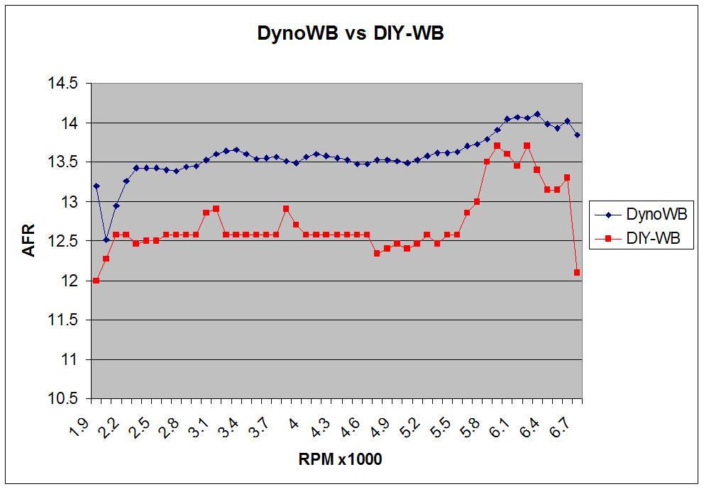
After extensive street tuning with NarrowBand-O2 (NB) and DIY WideBand
(WB) sensors, the first dyno test showed a very lean condition that was
tuned
out in the second and third dyno tests. After the dyno session,
the Dyno WB was plotted against the DIY WB data and shown above.
Unlike the previous
dyno "calibration" of the DIY setup that confirmed its values, this
dyno's WB showed a 1.0 AFR point difference. I'm taking all these
dyno tests at face value
until I can confirm/deny the calibration of the NB and DIY-WB sensors.
Quarter-Mile data (From Cecil County Dragway,
May 10, 2006)
|
700r4 w/10bolt |
T56 w/12bolt |
| Temp |
~50 |
~70
|
| Humidity |
|
|
| Baro |
|
|
| |
|
|
| R/T |
0.106 |
|
| 60' |
1.607 |
1.791 |
| 330' |
4.663 |
4.958 |
| 1/8 |
7.230 |
7.594 |
| Mph |
95.23 |
93.32 |
| 1000' |
9.461 |
9.825 |
| 1/4 |
11.351 |
11.716 |
| Mph |
119.53 |
119.80 |

ALDL scan data from Quarter Mile run. Note the 6500rpm shift points
and the optimal shift points determined below. Additionally,
the NB O2 sensor
showed the same Rich indications as on the dyno when fuel was added
over several tunes to get a good AFR value on the dyno WB sensor.
Optimal Shift Points
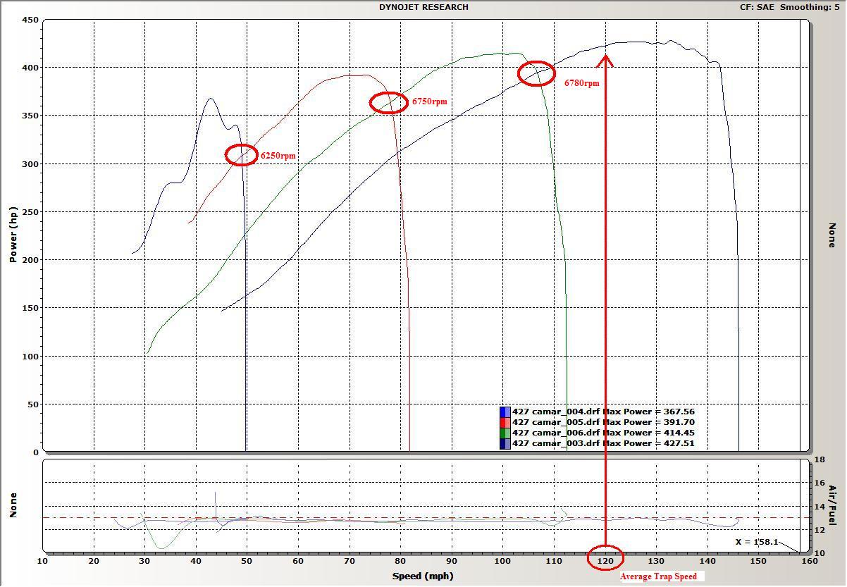
Plotting a Dyno run from each gear, versus speed (MPH) will result in
a crossover point where the car makes more power in the next gear.
Relating that MPH/Power back to engine RPM will give the optimal shift
point. In most Automatic cars, because of the wider ratio spacing,
the optimal point is at or near redline, in Manual cars the gear spread
may have lower optimal shift points. In the graph above you can see
the 1-2 curves cross at a low rpm, and I'm pretty sure it's a result of
the dyno missing alot of the 1st gear data since the engine spins up so
quickly. The 2-3 shift, and 3-4 shift (4th is 1:1 in T56) are probably
a better indication of where I should be shifting with this drivetrain.
TPI Intake duct restriction testing:
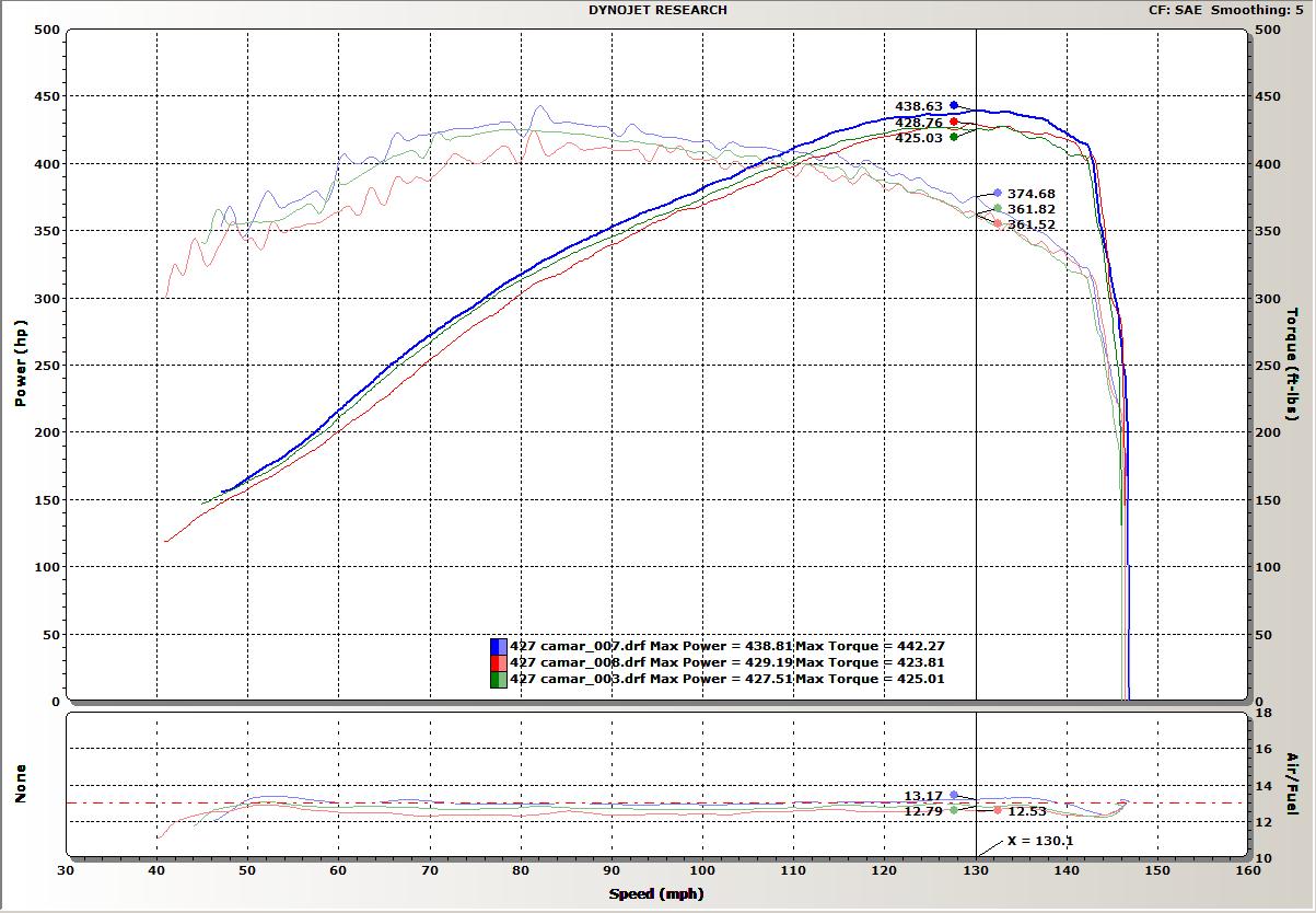
Several friends have had issues with vacuum building up as RPMs increase,
on their big bore TPI motors. I too have witnessed this with my 427sbc.
In
dyno tests in the past with my 350 and 383 motors, I've noticed little
to no gain by removing the K&N stock-style filters, or the entire ported
stock intake duct.
These previous motors ran with a 58mm TPI throttlebody (TB) and never
exhibited a wide-open-throttle (WOT) vacuum increase.
I dyno tested the 427 motor with the 58mm TB (~1050cfm), with and without
the intake duct and the vacuum increase remained. I purchased to
a monoblade
unit (1300cfm) and lent it to a friend, who found it didn't help his
WOT vacuum, and my initial testing with it also confirmed that my motor
also still pulled WOT
vacuum as RPMs increased. (Green003 dyno test, and top
ALDL scan above). I ran another dyno test with the K&N filters
removed, and while better, still
exhibited an increasing vacuum with increasing WOT RPM. (Blue007
dyno test and middle ALDL scan above). The final test was with
the entire TPI duct
pulled off, resulting in a bare TB opening. (Red008 dyno test, and
bottom ALDL scan above). The WOT vacuum was practically gone, and is now
suspect as
being a common restriction of BOTH the 58mm TB AND the TPI intake duct
on big-bore motors. (The intake duct is likely to flow around 1000-1100cfm
and with either it or the 58mm TB are installed, will limit airflow
to that cfm rating)
Although the last dyno run showed little or no Horsepower gain from
the first run, (while increasing over 10hp in the 2nd run) it should be
noted that the fueling
increased on the third run (perhaps from the new found vacuum changes)
and should be able to gain a significant increase with tuning.
The stock intake duct is planned to be modified for increased airflow
to match the 1300cfm rating of the TB.
Spark Timing changes:
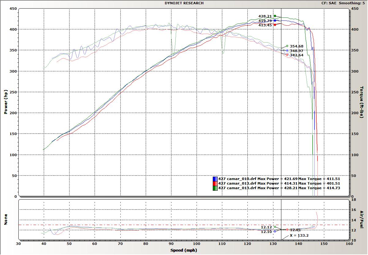
Within the fueling tune performed during these dyno tests, the beginning
WOT spark advance of 28degrees was increased to monitor for HP changes,
and any possible
spark knock detected. The 28deg run (Blue010) was followed by
a 30deg run (Red012) that lost power, and finally a 34deg run (Green013)
that added an additional
10hp over the original 28deg run.