 Info
on my '85 Camaro Z28
Info
on my '85 Camaro Z28
If you're looking to upgrading a '85 TPI ECM to a later MAF system, look here.
The '85 and '86-'89 TPI cars use a MAF sensor inline of the intake air flow to precisely measure the air flow and adjust A/F, etc. based on that reading. 1990-1992 TPI cars switched over to a MAP system (also referred to as Speed Density) where the ECM gets a estimated air flow based on engine vacuum. The change to MAP is rumored to be based on cost reasons for GM, but for performance engine builders, the limited air flow able to pass thru the MAF is also a consideration of changing to a MAP system.
I wanted to be able to quantitatively compare the MAF-vs-MAP systems on my vehicle to have a better understand the limits of each and how my car would react/benefit from both. To easily switch between the two systems, I set out to build/adapt both ECMs, different sensors, and wiring harness differences in a convenient manner to make switching back and forth between them as simple/easy as possible. After working thru the wiring diagrams and getting much valued help from the GMECM mailing list, I came up with a solution to equip my car with both set of sensors that are different, and build an adaptor cable between my existing ECM harness ('165 wired) and the newer ('730) ECM.
Note that you do not have to build the adaptor to change systems, you can easily reuse your MAF wiring and existing knock sensor engine wiring to hook the new MAP and knock sensor to. This is a more permanent solution if you're sold on Speed Density and don't want to switch back-forth between the MAF and MAP systems like I do.
This is a text file that has the required connector pin changes for the conversion. They are listed in order of the '165 connector pins as well as in order of the '730 connector pins. (Note that you need an additional ECM connector for the '730 ECM)
The pin naming nomenclature is shown in the above pinout/wiring diagrams.
'165 ECM connector pin changes for 92 ECM
A handy tool for repining GM harness connectors is the Lisle Terminal Tool, P/N 14900 and can be found here
Adaptor parts needed:
Total cost for the project is ~ $150 depending on what you can get thru salvage yards and what you have to purchase new..
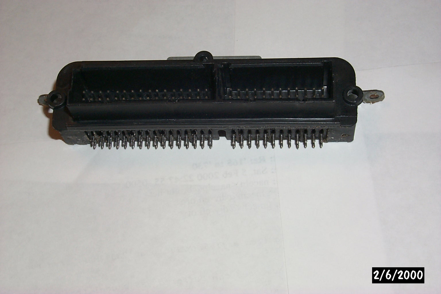
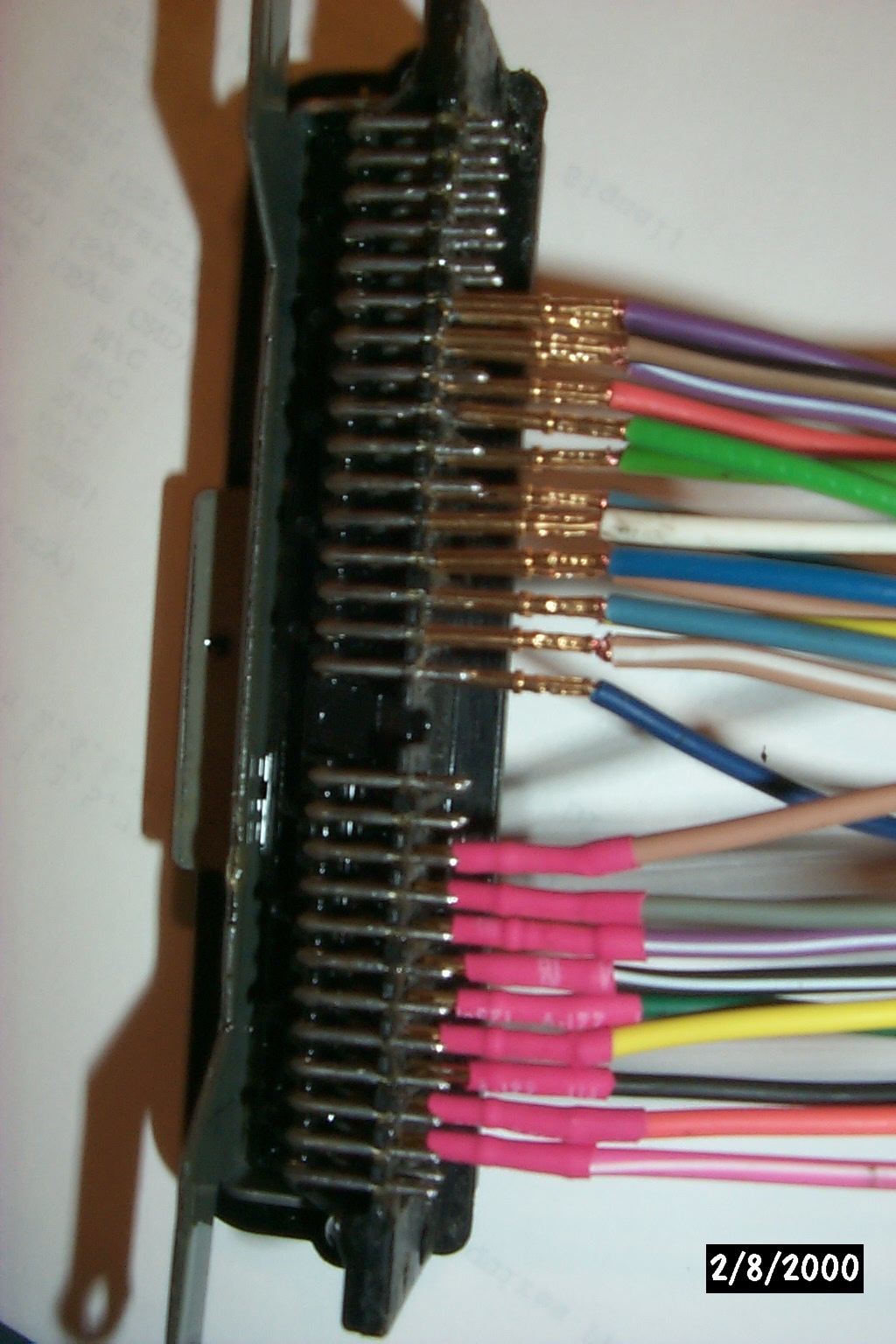
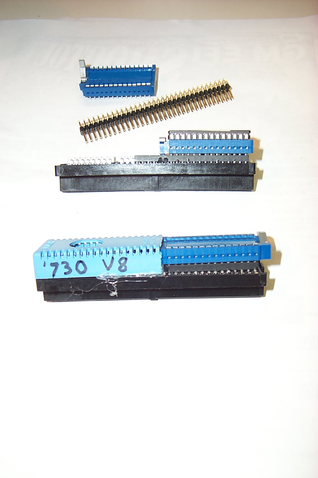
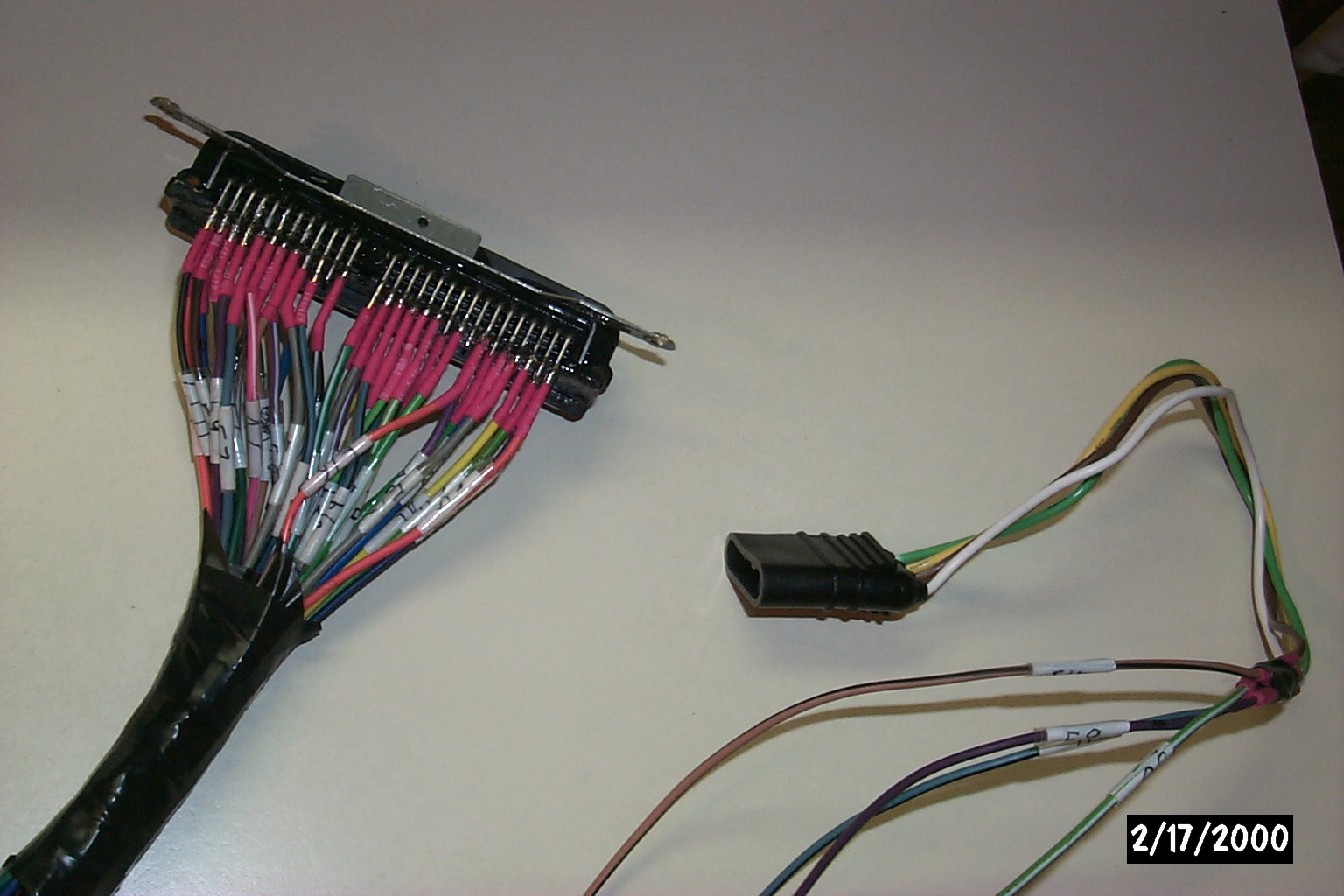
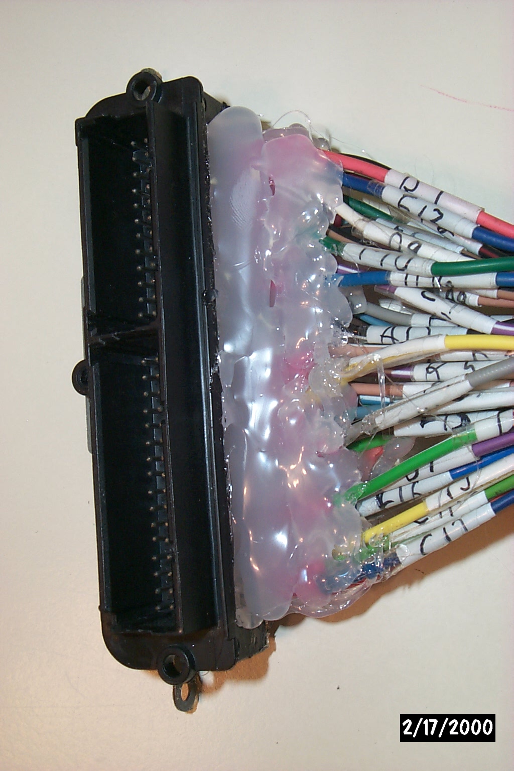
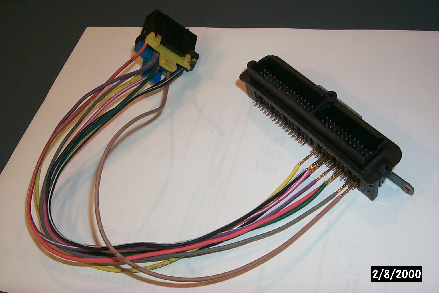
Common 24/32 ECM Header connector. Desoldered from Donated ECM
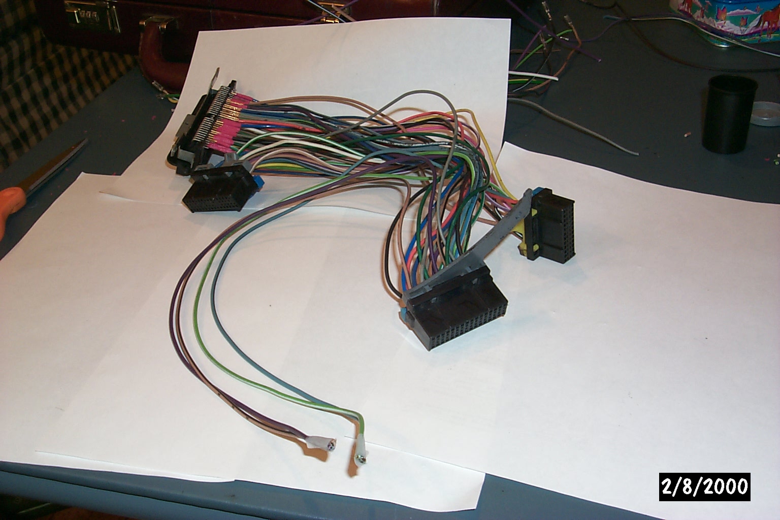
ECM Header connector next to ECM 24/32 harness for making Male/Female adaptor
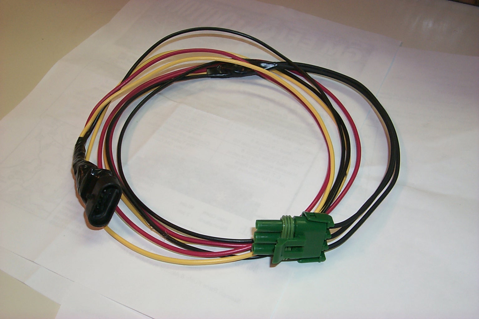
Knock sensor plug connector and '91 MAP sensor w/wires & vac tube. Pulled from junk yard

Knock sensor plug connector and '91 MAP sensor w/wires & vac tube. Pulled from junk yard
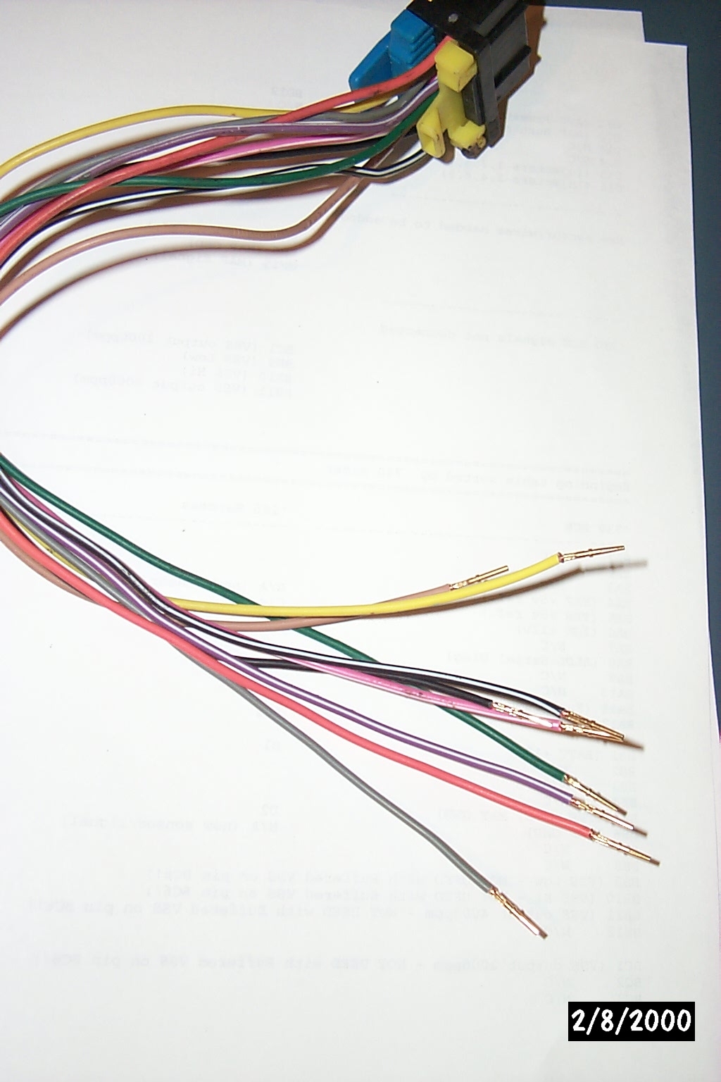
Crimp pins (AMP) used in RS232,etc. connectors hooked to harness connector wires
Close up of Crimp pins, some already heat-shrink covered
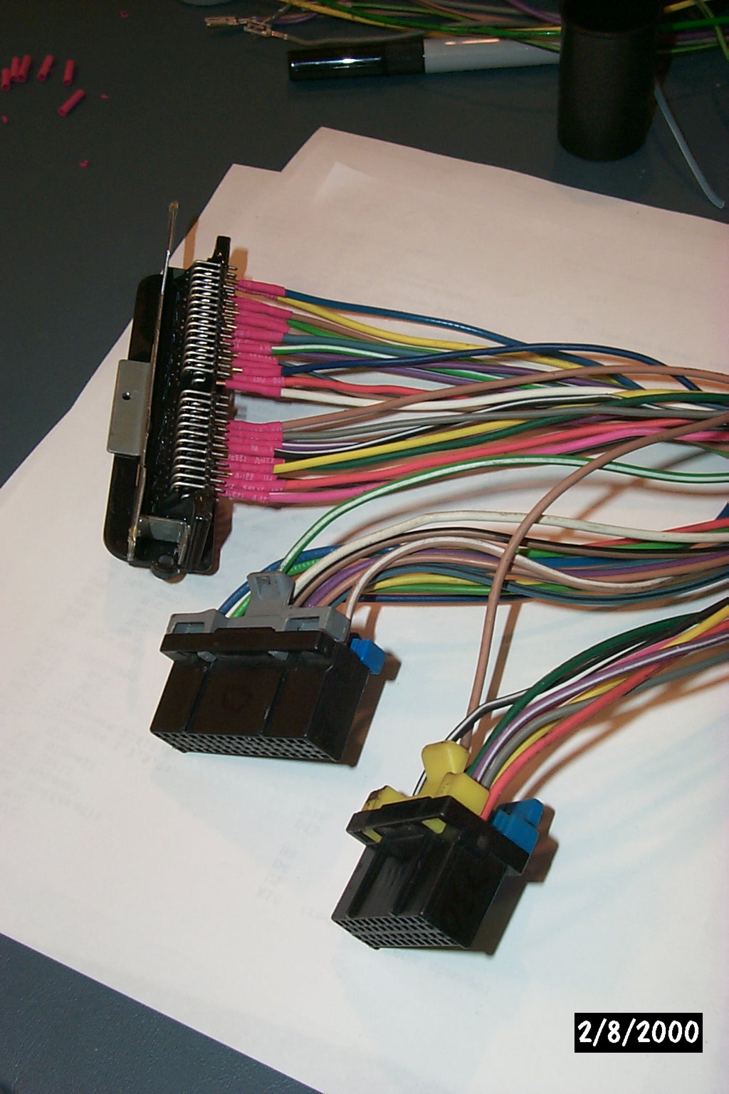
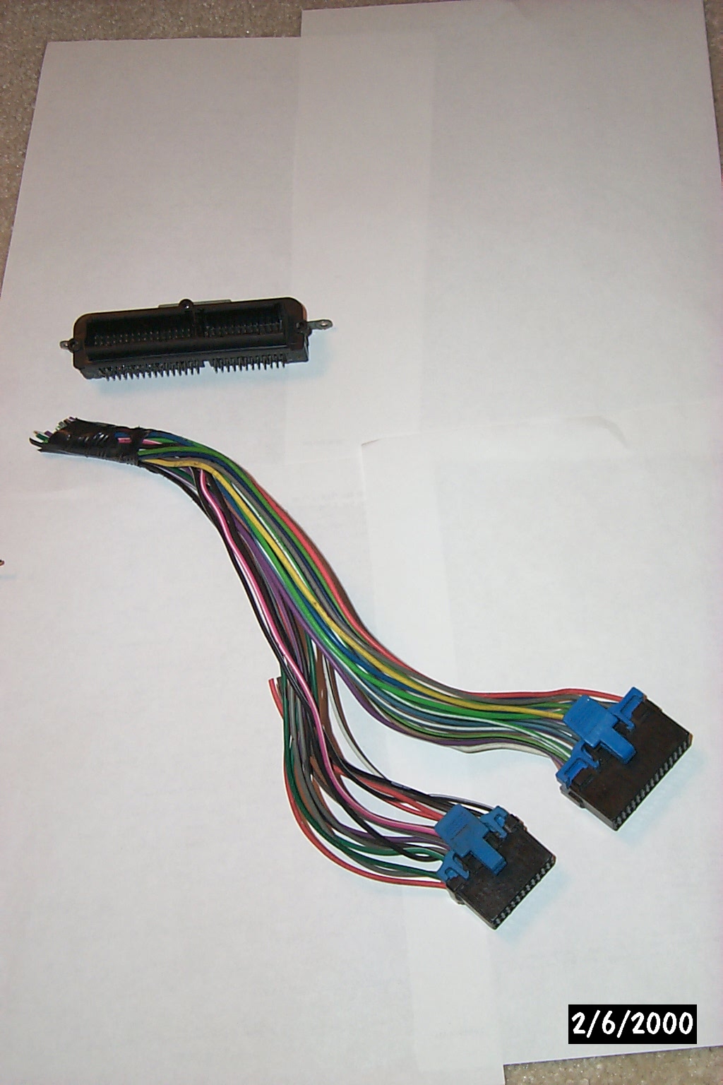
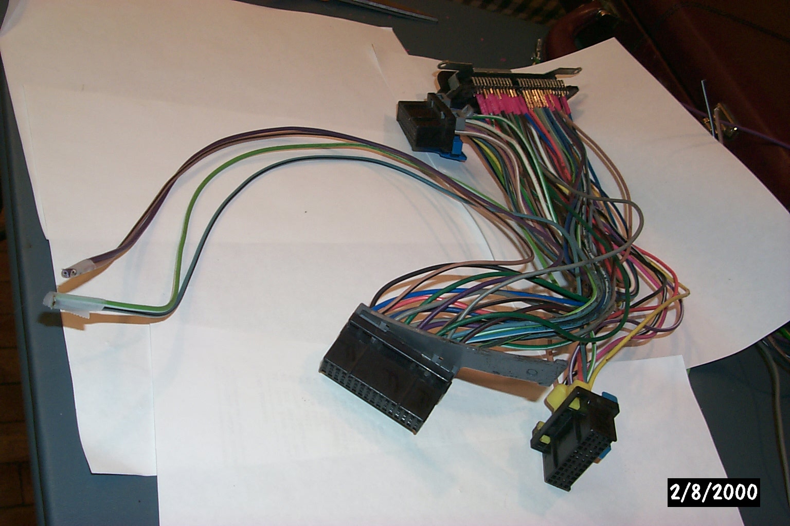
24 and 32 pin connectors modified and slipped onto header
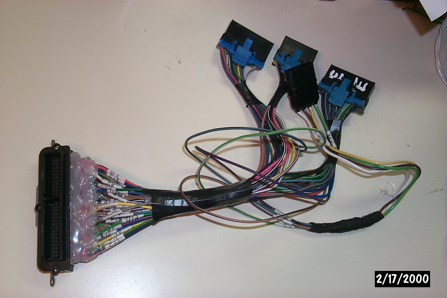
All three (24,32 and 32) connectors modified and slipped onto header
Long taped-off wires in foreground will hook to new MAP and Knock Sensors.
All three (24,32 and 32) connectors modified and slipped onto header
Long taped-off wires in foreground will hook to new MAP and Knock Sensors.
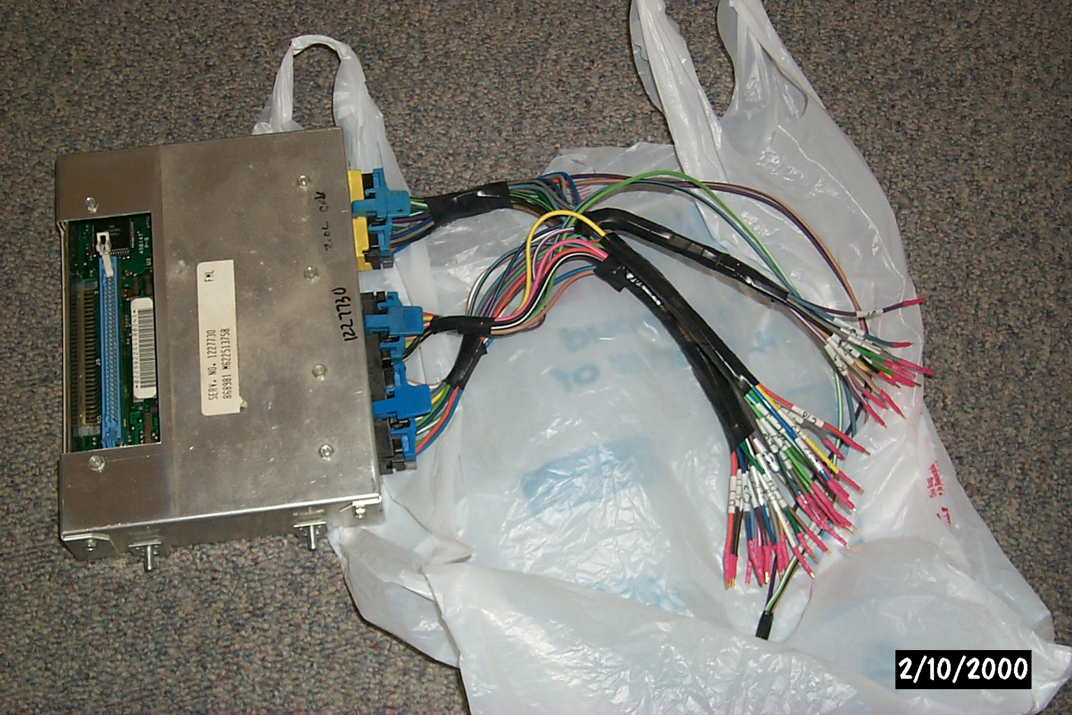
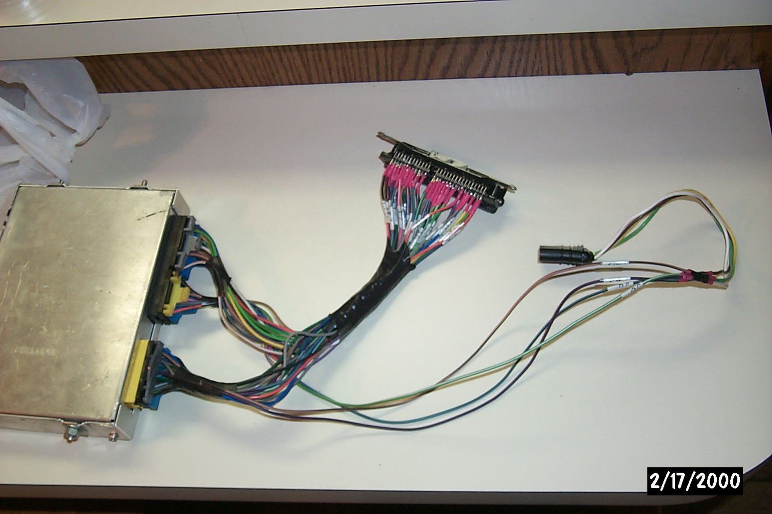
'730 ECM pluged into harness.
(labeled, but not soldered to pin header)
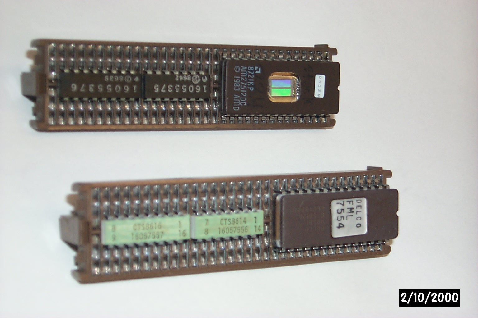
'730 and '165 MEMCALs.
'730 (lower) from L4 Cav, '165 from v8.
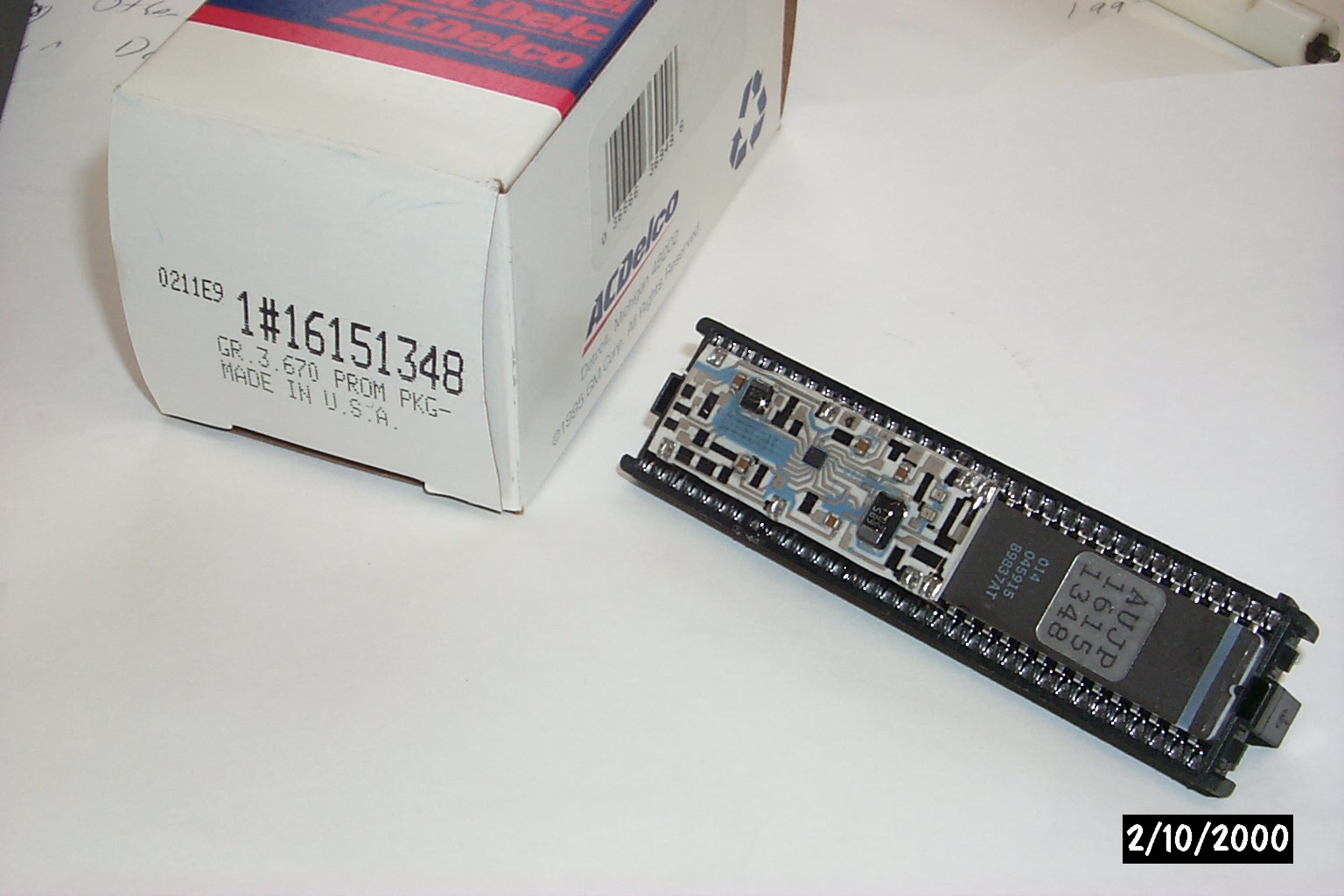
'730 V8 MEMCAL.
Knock Sensor circuit board built onto MEMCAL.
'730 (and '165) modified V8 MEMCAL.
low-profile ZIF into solded socket.
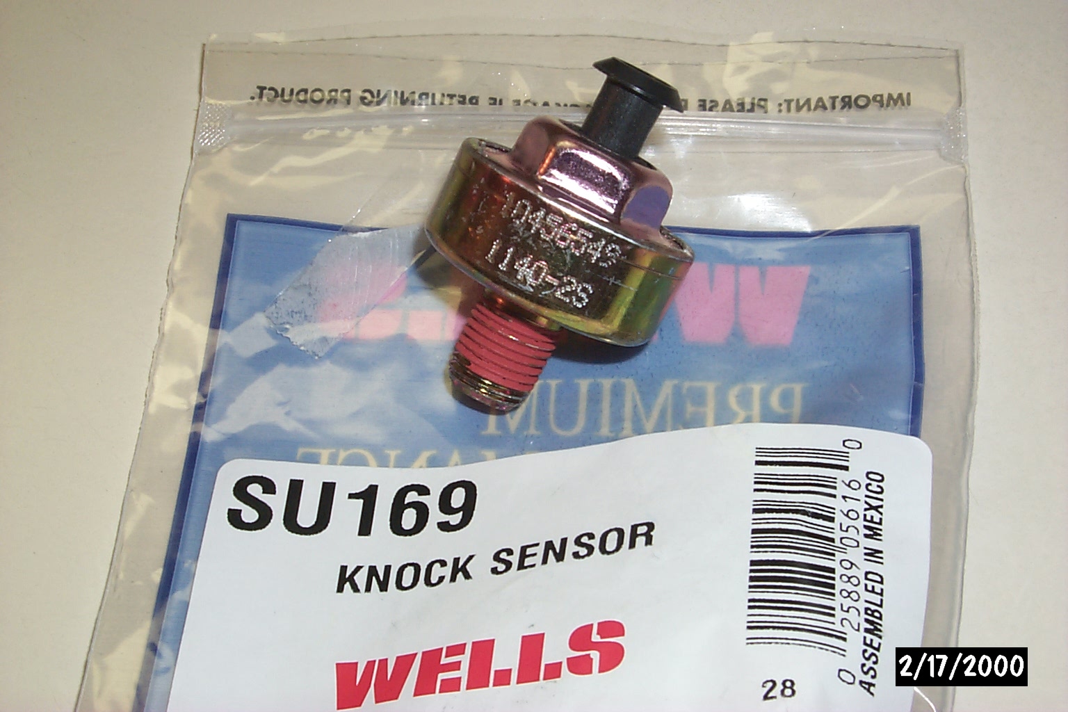
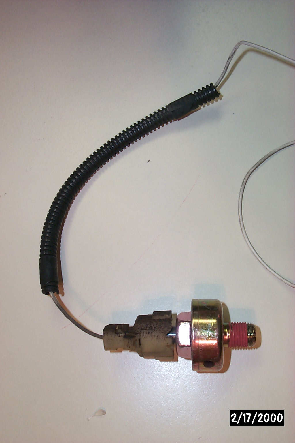
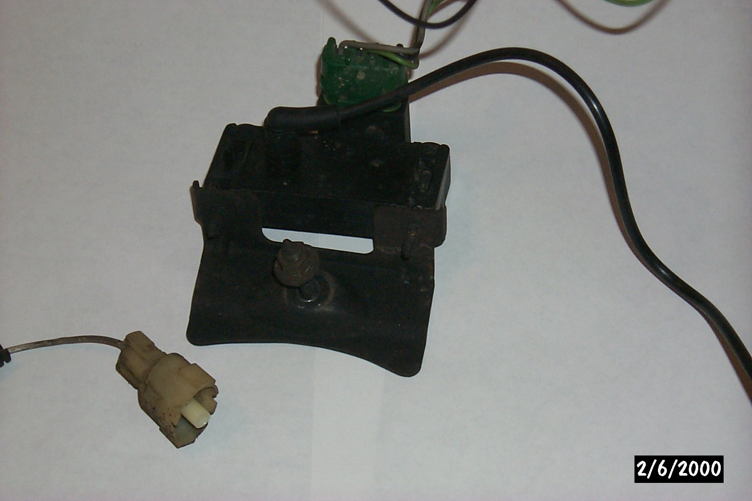
Knock Sensor w/ junkyard harness conn.

1/4" Vacuum port Y'd for MAP hookup
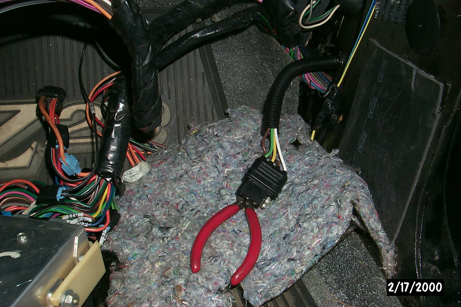
"Trailer Hitch"
wiring harness pulled thru firewall for MAP hookup to adaptor cable
ECM header with adaptor pins soldered on
ECM header with adaptor pins soldered on
ECM header with hot glue support casing
ECM header with hot glue support casing
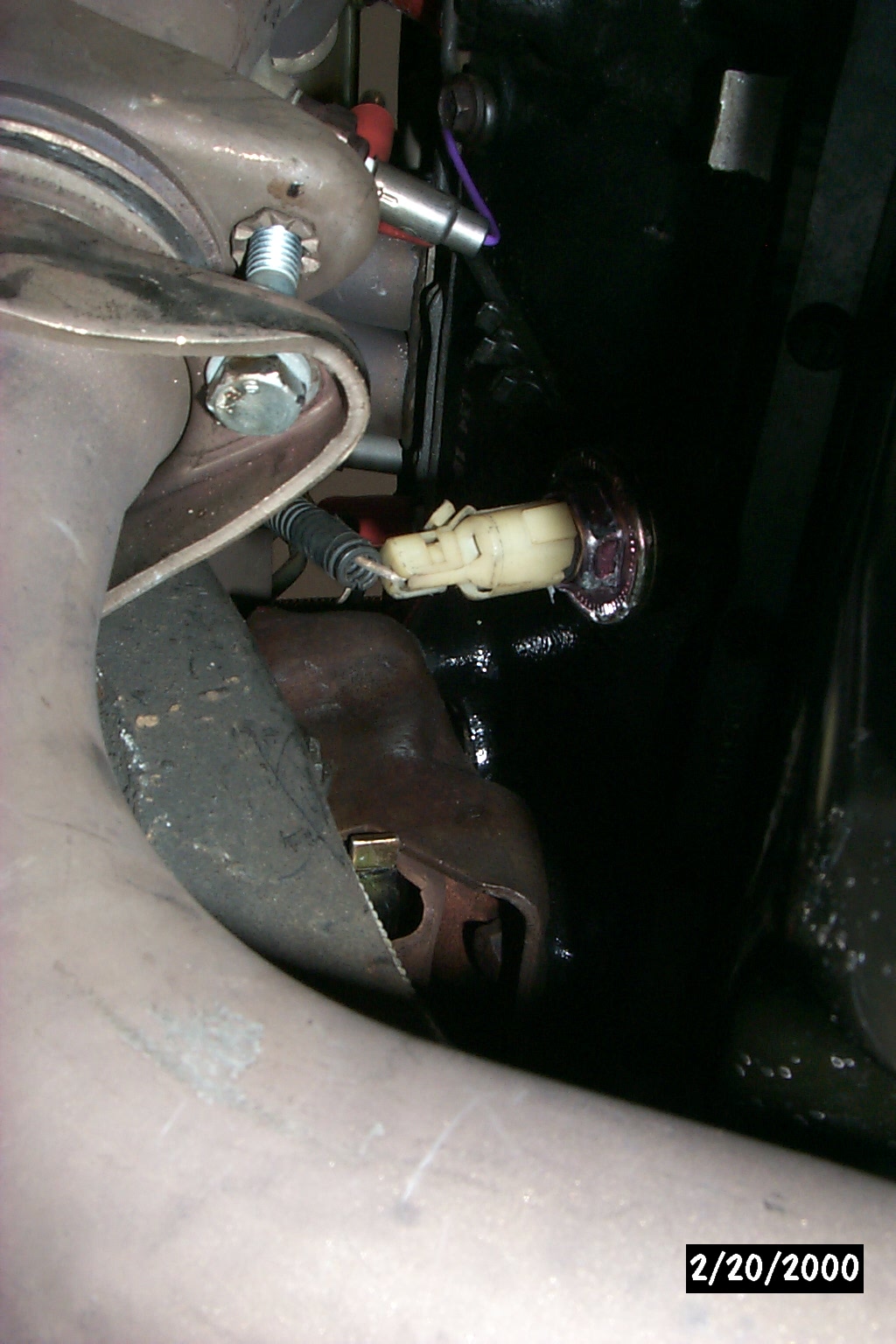
New (Second) knock sensor installed into drivers side of block

Knock sensor wire routed into CTS harness
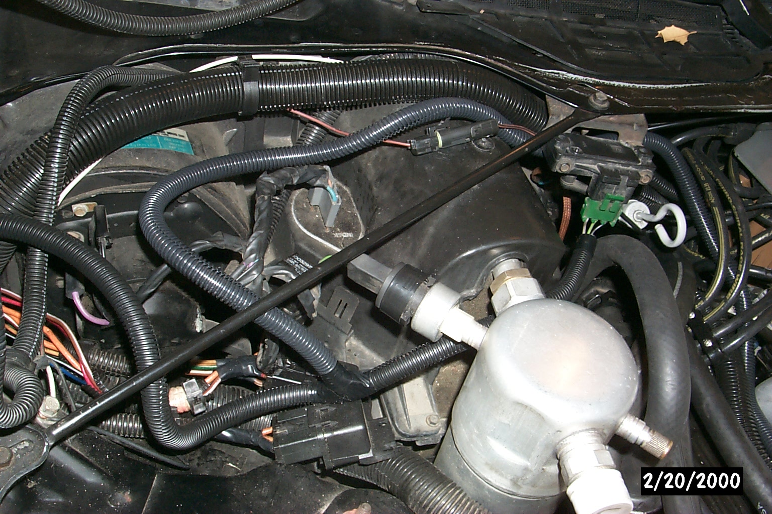
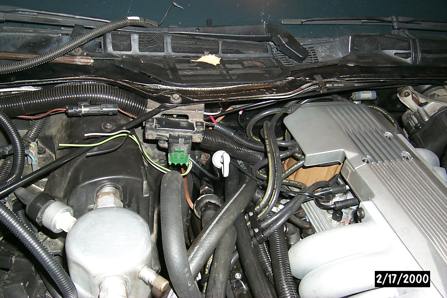
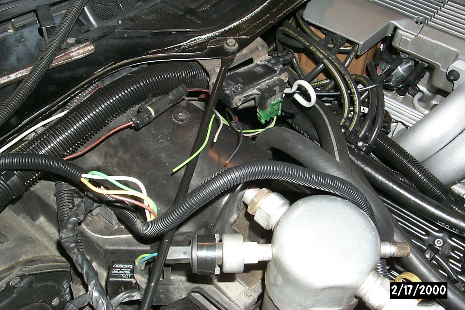
MAP and second knock sensor wired into engine-bay and down/thru firewall
Black plastic conduit used for all wiring for clean look.
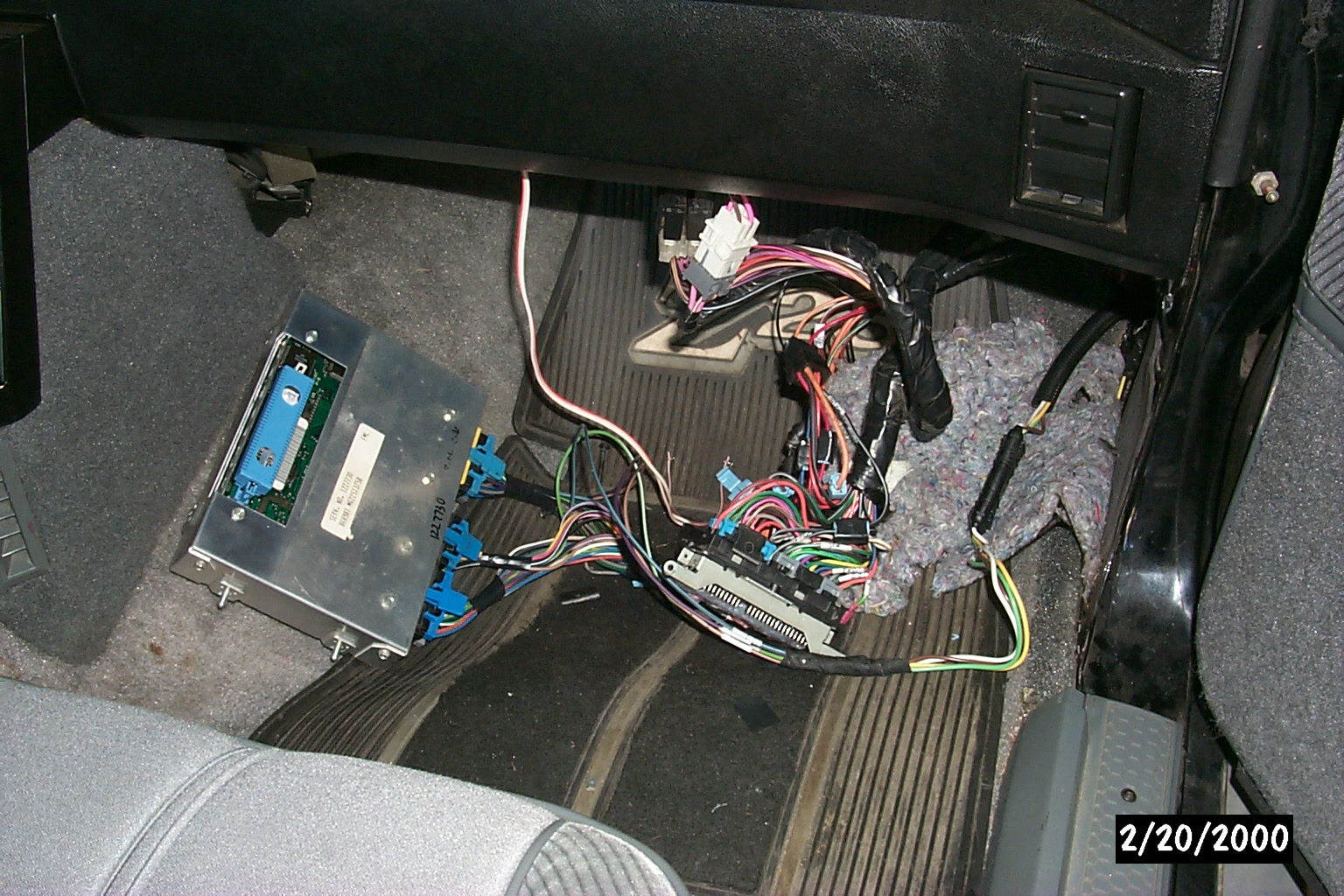
'730 ECM hooked to adaptor cable and onto "OEM" harness
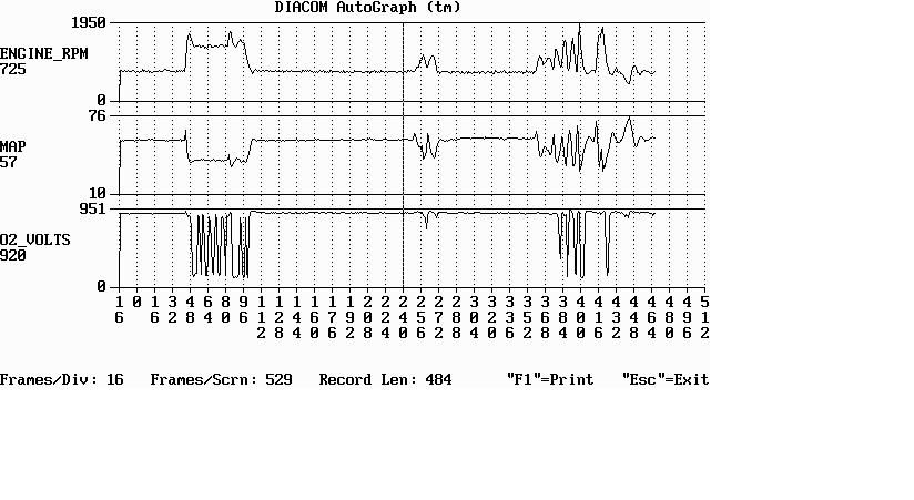
I started the car and gathered an initial ALDL scan to check sensors,etc. The car ran very poorly and the data showed it running VERY rich with the stock '92 5.7l calibration. I have enough preliminary data to start zoning in the EPROM. The ALDL data (after warmup) from the RPMs, MAP, O2 from the first start can be seen here
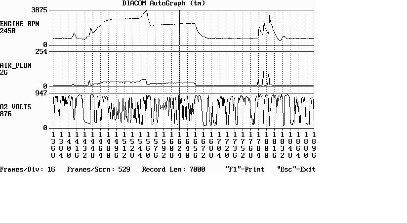
The adaptor was then unhooked and the '165 ECM reattached to prove they can be swapped easily. The ALDL data from the subsequent MAF is shown here .
A basic EPROM image and road test data will be forthcoming..

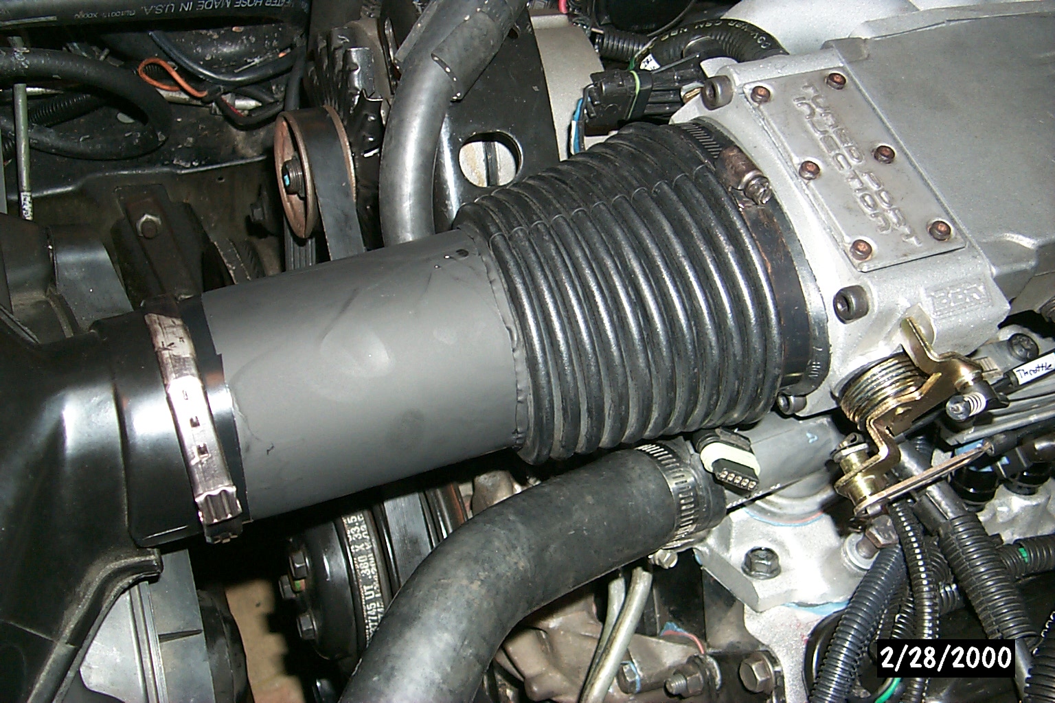
3-1/2" aluminum tube replacing MAF sensor
Cut from 3-1/2" diameter aluminum jar, 6" long. Painted "stealth" black
MAF hookup wire can be seen on thermostat housing
1 (MAP) 13.098@105 (let car shift to OD)
2 (MAP) 13.095@105 (let car shift to OD)
3 (MAF) 12.941@105 (kept car in 3rd to 5600rpm)
4 (MAF) 13.071@103 (let car shift to OD)
5 (MAF) 12.927@106 (kept car in 3rd to 5800rpm)
6 (MAP) 13.063@105 (kept car in 3rd to 5800rpm)
7 (MAP) 13.050@105 (kept car in 3rd to 5600rpm)
*note: all the runs had 60' times between 1.812 and 1.860 and so I feel are warranted for comparison..
The Bins used for the tests are a AUJP (Runs 1,2) , AUJP (Run 6) , AUJP (Run 7) variant used in the '730, and a ARAP variant used in the '165.
Diacom snapshots of the RPM,air flow,O2 for the best MAP and MAF runs..
Diacom snapshots of the RPM,Spark Adv (TDC relative),Knock retard for the best MAP and MAF runs..