 Info
on my '85 Camaro Z28
Info
on my '85 Camaro Z28
Back to my EPROM/ECM page
ECM Swap - Page Last Updated 990830
This project will detail the steps, parts, hints, techniques
for upgrading a 1985 GM TPI Engine Control Module (ECM) to a later model, having
several advantages over the older one.
The ECM that came in my 1985 Z28 Camaro with the TPI motor (VIN "F") is a
series 1226870 (870) control unit (car computer). This model was used in
the '85 F-body cars with TPI motors, Corvettes, and some 2.8l V6 (VIN "S" and
VIN "W") (*Reference*) cars. One major problem when tuning an EPROM for this ECM is that
the diagnostic data (ALDL) is transmitted at only 160 BAUD!. This works out
to about a 1.25 second interval between the 25 Bytes of data. I have only
been able to get about 6 to 8 data samples during a Quarter-Mile DragStrip
run which you can imagine does not provide much feedback for tuning. (sample data are at the bottom of the page in PDF format)
The ECM that came in 1986-1989 TPI Fbody's and Vettes is a series
1227165 (165). The ALDL data rate in this model can supply diagnostic data
at 8192 BAUD. The (expanded) data stream of 64 Bytes cycles through every
62.5 milliseconds (16 per second) at this BAUD rate.
The ECM is located up and behind the dash, on the passenger side of the car.
(Behind where a Glove Box would be in a older pre 80s car) The '85 ECM has
a large module attached to it on the outside that is the Burn Off Module referred to as the "MAS". This is replaced in the '86-'89 years with a pair of regular relays and logic contained within the ECM.
The ECM conversion/upgrade involves
10 repinning's in the stock '85 ecm harness connector
2 splices's between wires in the '85 ecm harness connector
1 wire removal in the '85 ecm harness connector
1 wire addition in the '85 ecm harness connector
A '165 ECM from a Donor '86-'89 TPI Fbody car
2 relays (and harness wiring) from a Donor '86-'89 TPI Fbody car
(Relay Harness plugs can be ordered thru a GM dealer under P/N 12101922 for about $25 each. -- Thanks to Kevin Irving for this tip..)
An EPROM configured to your Engine/Trans/etc.
A handy tool for repining GM harness connectors is the Lisle Terminal Tool, P/N 14900 and can be found here
Wiring Diagrams
85 Fbody ECM wiring diagrams 86 ECM pinout diagram
85 ECM wiring (MAF/MAS) diagram copy1/copy2 86 ECM wiring (MAF) diagram
Pin Change list (The real work of the swap.. 8-)
85 ECM connector pin changes for 86 ECM
Photos of my swap
August 26 1999 (Preparation)
1985 Stock ECM ('870) Side View
1985 Stock ECM ('870) MAS closeup
1985 Stock ECM ('870) EPROM area closeup
1985 Stock Wiring Harness (ECM connectors)
1985 Stock Wiring Harness (ECM connector A/B)
1985 Stock Wiring Harness (ECM connector C/D)
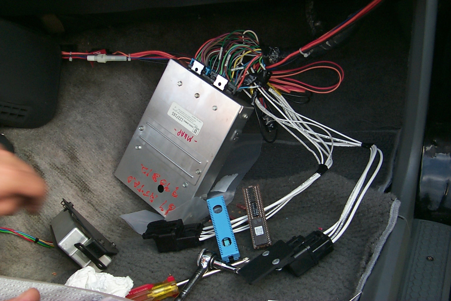
1986-89 '165 Series ECM (Full View)
'165 ECM MemCal modified.
CalPak sawed in half, ribbon cable runs to ZIF socket
1985 Stock FuelPump Relay on Drivers Side Engine bay Firewall
1985 Drivers Side Engine bay Firewall - mount points for "new" MAF Sensor and MAF Burn-off relays
MAF Sensor and MAF burn-off relays from a '87 (left) and '89 (right) Fbody (Top View)
MAF Sensor and MAF burn-off relays from a '87 (left) and '89 (right) Fbody (Side View)
MAF Sensor and MAF burn-off relays from a '87 (left) and '89 (right) Fbody (Bottom View)
MAF Sensor relay and harness connectors (MAF Sensor, MAF burn-off, Fuel Pump ) from a donor '87 Fbody
August 27-28 1999 (Repining/Splicing)
Pins pulled out (and labeled!) for getting repined
Pins are removed from the ECM connector by using a large paperclip and inserting
it into the outside edge hole of the connector. This takes a little finesse at first, but after the first couple you'll get the hang of it.
Doner relay harness labelled and ready for pull-through
Stock harness route thru fender, into enginebay
Relay harness routed into enginebay w/ new MAF sensor and burn-off relays attached
Relay harness routed into enginebay w/ new MAF sensor and burn-off relays attached (closeup)
Repinning and splicing completed
The original "MAS" connector is shown inthe uppper-left. It has three (3) splices into it. The Red and Blue lines are directly to the MAF. The large Orange wire is the +12V that runs from the ECM into the Fuel-pump, new MAF sensor, and new MAF burn-off relays. (Feeds relay connector "E" on all three relays as shown in the 86 ECM wiring (MAF) diagram from B1 and C16 on ECM.
All done and hooked to "new" (165) ECM
August 29 1999 (ZIF Socket Extension, All Done!)
30-pin Ribbon Cable wired to project board w/ 28-pin ZIF socket installed
See ECM calpak image for other end.
ZIF board installed in passenger kickboard, below ECM mounted in dash
ZIF board installed in passenger kickboard, below ECM mounted in dash (closeup)
FRUITS OF MY LABORS
Excel Spreadsheet of 1/4 Mile test data from my old ECM (870) and the newly installed ECM (165)
Complete ALDL data from two 1/4-mile runs, the only difference is the ECM. File is in Excel-97 format and has example graphs showing MAF measured Air Flow for both. (let the tuning begin.. 8-)
PDF graphs of Above Air-Flow data for
870 ECM
and
165 ECM